A weakness in the OpenBox S-9 and possibly the other models is the LNB voltage. I suspect these are being damaged by connecting a second receiver to the loop thru. The OpenBox like other receivers has excellent short circuit protection, but not stray voltage protection. So when you connect a second receiver to the OpenBox and one is set to vert, and the other is horz, zzzap. 13 and 18 volts don't mix well. Use an external splitter with the OpenBox.
This problem can be very elusive as under certain conditions the receiver will still work after it has been damaged, but cannot pull too heavy a load. It might still run one lnb, but connected to a system with switches or motors will bring it down. Many people have have measured the lnb voltage at the back of the receiver and with nothing connected the voltage may read normal.
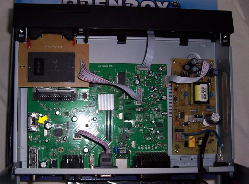
If your receiver is out of warranty you can open it up and make these checks and possibly repair it yourself.
You need to check the LNB regulator mounted on a heat sink near the tuner, and a troublesome resistor near it. (see yellow arrow in photo)
Connect your receiver with a short coax to a lnb or to your dish system coax for loading. Power it up and measure the voltage on the three terminals on the regulator. I've numbered them from left to right 1-2-3 ( see photo).
Horz. channel
1=18v output
2=20v control v.
3=25v input
Vert. channel
1=13v
2=15v
3=25v
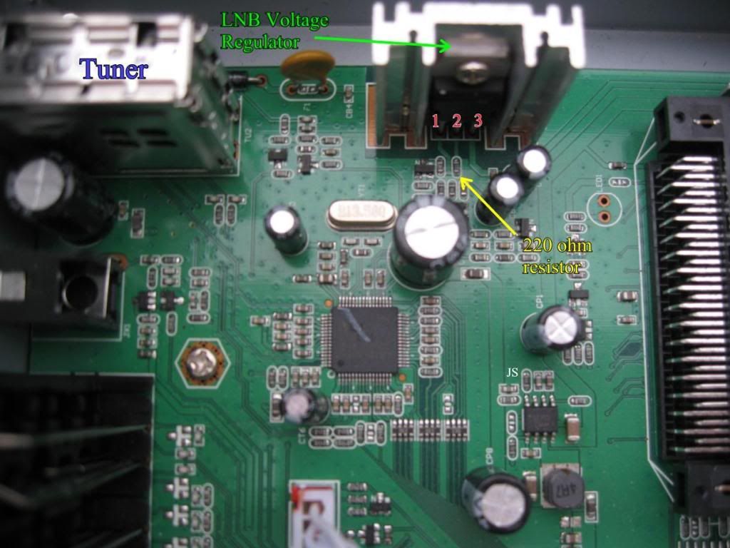
Next with the power off (back switch) check the value of the small black resistor that is in line with the center terminal of the regulator. It should measure 220 ohms "in circuit"
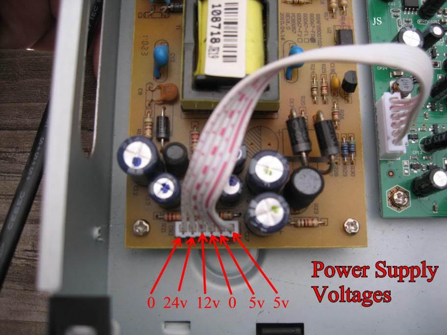
Now with the power back on check the voltage of the power supply. It has a flat white ribbon connector and you will need a pin or small wire on the end of your probe to slip down the top of the connector and get at each circuit. The voltage values are marked on the board and also in my photo.
This problem can be very elusive as under certain conditions the receiver will still work after it has been damaged, but cannot pull too heavy a load. It might still run one lnb, but connected to a system with switches or motors will bring it down. Many people have have measured the lnb voltage at the back of the receiver and with nothing connected the voltage may read normal.
If your receiver is out of warranty you can open it up and make these checks and possibly repair it yourself.
You need to check the LNB regulator mounted on a heat sink near the tuner, and a troublesome resistor near it. (see yellow arrow in photo)
Connect your receiver with a short coax to a lnb or to your dish system coax for loading. Power it up and measure the voltage on the three terminals on the regulator. I've numbered them from left to right 1-2-3 ( see photo).
Horz. channel
1=18v output
2=20v control v.
3=25v input
Vert. channel
1=13v
2=15v
3=25v
Next with the power off (back switch) check the value of the small black resistor that is in line with the center terminal of the regulator. It should measure 220 ohms "in circuit"
Now with the power back on check the voltage of the power supply. It has a flat white ribbon connector and you will need a pin or small wire on the end of your probe to slip down the top of the connector and get at each circuit. The voltage values are marked on the board and also in my photo.
Last edited:
")