
I have a SL3 and SWS8(not green label),3 H21 recievers and a HR22.
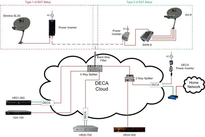
Would this diagram be correct for MVR?If not,where is it wrong and how so?Am I missing any components(BS Filters?)
I tried to search it,but I couldnt get reasonable results.Any help appreciated.
LNB---->PI---->BS filter--->SWS8
SWS8--->DECA--->H21
SWS8--->DECA--->H21
SWS8--->DECA--->H21
SWS8--->DECA--->HR22
SWS8--->DECA--->MODEM
••••••••••• |
••••••••••• |
••••••••••• ------>POWER SUPPLY
Last edited:
![SWM DECA install[10].jpg](https://cdn.satelliteguys.us/xen/data/attachments/43/43029-c2967fa038a9f65d92cbceffafe43f73.jpg?hash=wpZ_oDip9l)