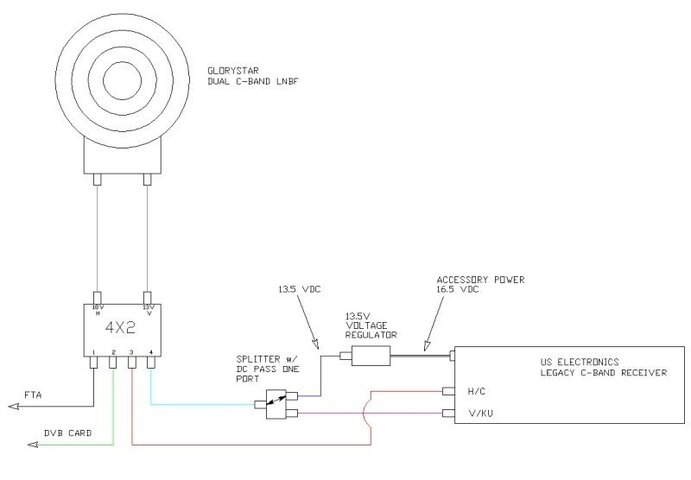
I had some time this weekend to test an idea I had. My goal was to share a dual c-band lnbf with an FTA receiver, a DVB card and my C-Band receiver with a 4X2 multi-switch. The issue was with the c-band receiver. It does not support lnbf 13/18V switching of polarities.
My US Electronics c-band receiver has two inputs for lnb's. They can be configured as one C and one KU, OR as one C-H and the other C-V. I decided to forsake the KU at this time as I rarely ever use it. I had already ordered the dual lnbf from a sponsor here before I knew if I could make it work.
The receiver outputs 16.5V for each lnb no matter how they are configured. The 16.5V would automatically force the switch/lnbf to the horizontal polarity. So I wondered how I could have access to the vertical polarity.
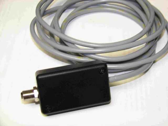
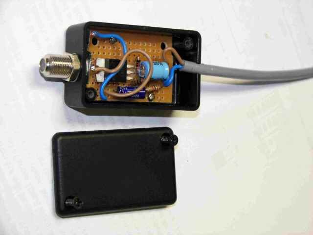
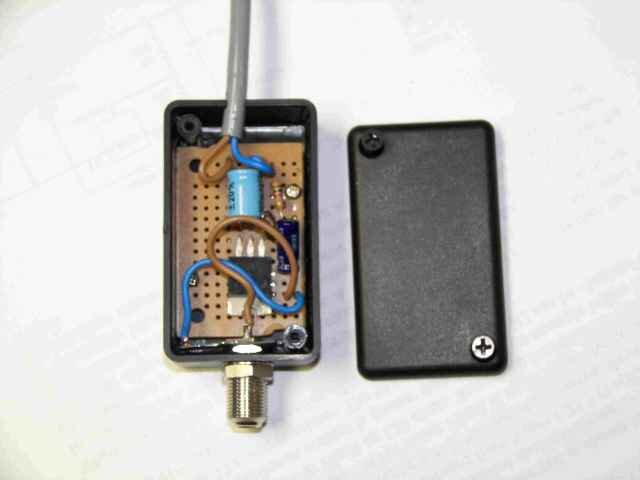
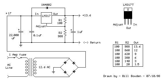
The US Electronics Legacy receiver provides 16V for accessories through spring terminals on the back of the receiver. It provides 500ma max less already powered lnb's. The new dual lnbf specs show it draws a max 100ma, so I thought …. I decided to build a small voltage regulated power supply to regulate to 13.5V. I could use the accessory power from the receiver to power it. I had some fairchilds LM317 voltage regulators on hand from a PIC programmer I built a while back. I disassembled an old dish 1000 receiver to get an F-connector. My idea was to hook up H directly to the switch, then from the receiver V, run out to the blocked port of a splitter, then send the regulated 13.5 V through the pass port. The LM317 provides up to 500ma without a heat sink, and has built in short/overcurrent/heat protection.
Long story short… I got er done!
The Legacy receiver also provides a spring terminal connection that goes high when H is selected and low when V is selected. Another connection goes high when C is selected and low when KU is selected. If I wanted to add KU back in the mix, I think I can do it.
I bought two of these receivers for just under $50 shipped.
Attached are some pictures.
The LM317 schematic is what I started from, obviously I didn't need the bridge or that large cap.
Comments are welcome.
My US Electronics c-band receiver has two inputs for lnb's. They can be configured as one C and one KU, OR as one C-H and the other C-V. I decided to forsake the KU at this time as I rarely ever use it. I had already ordered the dual lnbf from a sponsor here before I knew if I could make it work.
The receiver outputs 16.5V for each lnb no matter how they are configured. The 16.5V would automatically force the switch/lnbf to the horizontal polarity. So I wondered how I could have access to the vertical polarity.
The US Electronics Legacy receiver provides 16V for accessories through spring terminals on the back of the receiver. It provides 500ma max less already powered lnb's. The new dual lnbf specs show it draws a max 100ma, so I thought …. I decided to build a small voltage regulated power supply to regulate to 13.5V. I could use the accessory power from the receiver to power it. I had some fairchilds LM317 voltage regulators on hand from a PIC programmer I built a while back. I disassembled an old dish 1000 receiver to get an F-connector. My idea was to hook up H directly to the switch, then from the receiver V, run out to the blocked port of a splitter, then send the regulated 13.5 V through the pass port. The LM317 provides up to 500ma without a heat sink, and has built in short/overcurrent/heat protection.
Long story short… I got er done!
The Legacy receiver also provides a spring terminal connection that goes high when H is selected and low when V is selected. Another connection goes high when C is selected and low when KU is selected. If I wanted to add KU back in the mix, I think I can do it.
I bought two of these receivers for just under $50 shipped.
Attached are some pictures.
The LM317 schematic is what I started from, obviously I didn't need the bridge or that large cap.
Comments are welcome.
")
")

