
I'm in the process of revamping my FTA systems to accommodate a bunch of new dishes and LNBs. To take advantage of the opportunity, I will be sporadically posting documentation of some of the odd changes I'm making along the way.
First up is the DG-380 HH motor used to drive my 1.2m that has a Invacom QPH-031 LNBF (orthofeed for H&V FSS and L&R DSS). I originally set this up to feed all four inputs of a powered 4x8 switch, which in turn feeds 4x1 DisEqC switches, one for each receiver. The other DisEqC ports went to my other dishes, all of which are motorized. One of my receivers (actually a USB box) was designated as the master to control the motors. The switching matrix for all of the dishes is located a substantial distance from the 1.2m, so when I installed it I used a power inserter and a F tee connector to split off the commands and power for the motor from the LNBs. That meant I had five lines, 4 from the LNBF outputs and 1 to the motor, running between the 1.2m and the switch matrix. This seemed a better approach than running a cable to the motor and back to the switch, or requiring the master to always drive the same band/polarity to move the dish. It also kept the LNB outputs from going through the motor.
Afterwards I had one of my new USB boxes fry while driving the 1.2m, a few minutes after first hooking it up. The manufacturer chalked this up to infant mortality and sent a replacement box, which has worked fine for the past half year. Nevertheless I wasn't thrilled about the load placed on the USB box, given my experience and its relatively lightweight power supply. What I wanted was to have the motor power for the DG-380 separated from the receiver commands. That way I could use a beefy power supply to turn the motor and relieve the receiver from supplying any power at all (the 4x8 switch already provides independent power to the connected LNBs. The receiver switches voltages for H&V and 22 KHz on/off, but at a miniscule current). Because the motor power is a constant 18V (or whatever you want it to be), the drive speed doesn't drop if a V polarization is selected.
The best place to make this mod seemed to be in the DG-380 itself. It already has two connectors, so no external changes would be required. This voids the motor warranty, but I could care less. The mod can probably be done in a similar fashion to other motors. The steps are:
1. Loosen and remove the three screws on the bottom of the motor that hold on the top cover.
2. Remove the top cover.
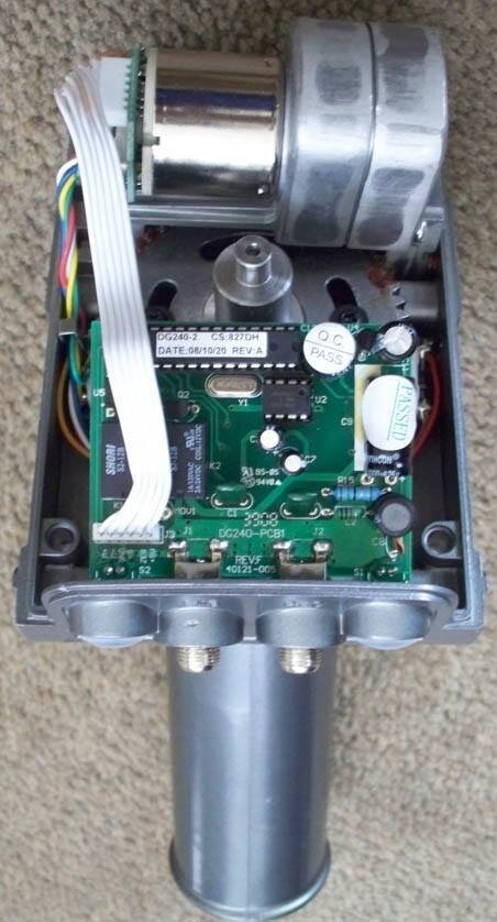
3. Loosen and remove both F-connector hex nuts that mount the circuit board to the case (see "DG-380 Opened" photo). A deep socket worked for me.
4. Disconnect the ribbon cable tying the circuit board to the motor.
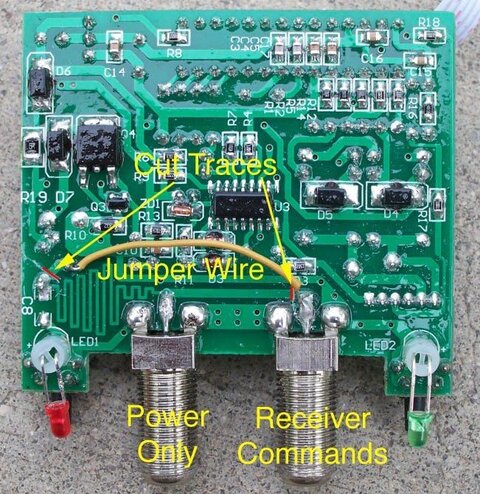
5. Cut the two traces indicated in the "DG-380 Circuit Mod" photo and add the jumper wire shown. You should check that the traces are broken with a meter, but be aware there is a nonconductive coating over the board, so you may have to puncture it or scrape some off to make a valid test.
6. That's it. Reassemble the case.
The photo shows which connector accepts the power for the circuit and the motor (right side when looking from the back when the motor is mounted on the mast) and which connector accepts DisEqC/USALS commands (left side). Note the circuit board photo is from underneath, so don't get crossed up.
Other observations:
When I was testing the mod with my USB box, the receiver would not send commands when directly connected to the motor's command port. I could see this on a scope. It apparently wants a little current draw to operate. I simply hooked a spare DisEqC switch in between the motor and the USB box and all was well. That pretty much mimics how this will be set up in real life.
Because both F-connector ports are used up, the receiver commands have to be split from the line(s) to the LNB outputs. Of course this is exactly what I wanted to do in the first place. There are many ways to do this, but a power inserter, F-tee connector and an optional terminator makes a clean install. I put the tee in-line with the receiver cable, and used a M-M F connector to connect it to the inductor-only side of the power inserter. I put a 75 ohm terminator on the capacitor-only side. The port common to both drives the receiver command line.
First up is the DG-380 HH motor used to drive my 1.2m that has a Invacom QPH-031 LNBF (orthofeed for H&V FSS and L&R DSS). I originally set this up to feed all four inputs of a powered 4x8 switch, which in turn feeds 4x1 DisEqC switches, one for each receiver. The other DisEqC ports went to my other dishes, all of which are motorized. One of my receivers (actually a USB box) was designated as the master to control the motors. The switching matrix for all of the dishes is located a substantial distance from the 1.2m, so when I installed it I used a power inserter and a F tee connector to split off the commands and power for the motor from the LNBs. That meant I had five lines, 4 from the LNBF outputs and 1 to the motor, running between the 1.2m and the switch matrix. This seemed a better approach than running a cable to the motor and back to the switch, or requiring the master to always drive the same band/polarity to move the dish. It also kept the LNB outputs from going through the motor.
Afterwards I had one of my new USB boxes fry while driving the 1.2m, a few minutes after first hooking it up. The manufacturer chalked this up to infant mortality and sent a replacement box, which has worked fine for the past half year. Nevertheless I wasn't thrilled about the load placed on the USB box, given my experience and its relatively lightweight power supply. What I wanted was to have the motor power for the DG-380 separated from the receiver commands. That way I could use a beefy power supply to turn the motor and relieve the receiver from supplying any power at all (the 4x8 switch already provides independent power to the connected LNBs. The receiver switches voltages for H&V and 22 KHz on/off, but at a miniscule current). Because the motor power is a constant 18V (or whatever you want it to be), the drive speed doesn't drop if a V polarization is selected.
The best place to make this mod seemed to be in the DG-380 itself. It already has two connectors, so no external changes would be required. This voids the motor warranty, but I could care less. The mod can probably be done in a similar fashion to other motors. The steps are:
1. Loosen and remove the three screws on the bottom of the motor that hold on the top cover.
2. Remove the top cover.
3. Loosen and remove both F-connector hex nuts that mount the circuit board to the case (see "DG-380 Opened" photo). A deep socket worked for me.
4. Disconnect the ribbon cable tying the circuit board to the motor.
5. Cut the two traces indicated in the "DG-380 Circuit Mod" photo and add the jumper wire shown. You should check that the traces are broken with a meter, but be aware there is a nonconductive coating over the board, so you may have to puncture it or scrape some off to make a valid test.
6. That's it. Reassemble the case.
The photo shows which connector accepts the power for the circuit and the motor (right side when looking from the back when the motor is mounted on the mast) and which connector accepts DisEqC/USALS commands (left side). Note the circuit board photo is from underneath, so don't get crossed up.
Other observations:
When I was testing the mod with my USB box, the receiver would not send commands when directly connected to the motor's command port. I could see this on a scope. It apparently wants a little current draw to operate. I simply hooked a spare DisEqC switch in between the motor and the USB box and all was well. That pretty much mimics how this will be set up in real life.
Because both F-connector ports are used up, the receiver commands have to be split from the line(s) to the LNB outputs. Of course this is exactly what I wanted to do in the first place. There are many ways to do this, but a power inserter, F-tee connector and an optional terminator makes a clean install. I put the tee in-line with the receiver cable, and used a M-M F connector to connect it to the inductor-only side of the power inserter. I put a 75 ohm terminator on the capacitor-only side. The port common to both drives the receiver command line.


")


