Naughty Mods III: 6x8 Switch with Power Insertion

Status
Please reply by conversation.

pendragon

SatelliteGuys Pro
Original poster
Oct 13, 2008
1,101
66
Sometime back I posted details on modifying the WNC SWA-48 4x8 switch to have all inputs wired for a 18V supply voltage for driving LNBs that don't think in terms of 18/13V and 22 KHz. At the time this switch had a lot going for it (1) it was already powered, (2) it had good headroom, (3) it could pass up to 2150 MHz (barely), (4) the case was easy to open and (5) it was going for nothing on eBay.

I ran into some bizarre problems the other day that ultimately turned out to be a bad tap, but along the way I decided the WNCs are not the best choice for bandstacked and universal LNBs. That will be fodder for another thread, because I measured a lot of switches and amps, resulting in some interesting data. But the bottom line was I went looking for another 4x8 switch that could really pass 950-2150 MHz in its sleep.

I finally decided to try the Zinwell WB68, even though it is powered by receiver(s) rather than a wart. The prices are now much lower than a few months ago and it is designed for DirecTV's Ka/Ku system that requires 250-750, 950-1450 and 1650-2150 MHz IF. The first one arrived yesterday and after some quick performance checks I was sold.

Even though the WB68 is a 6x8 switch, only four inputs are readily accessible to FTA receivers. The other two input are called 'Flex Ports' and supposedly require special codes to be sent for their selection. I can't imagine it would be that hard to figure this out, but I couldn't find anything on the web indicating someone has done it. In the meantime this makes the WB68 an effective 4x8 switch, using 18/13V and 0/22 KHz for selection purposes. That was the fly in the ointment for me because I want all the inputs to send +18V to my LNBs. So out came the weapons and open came the WB68 to see what could be done about this.

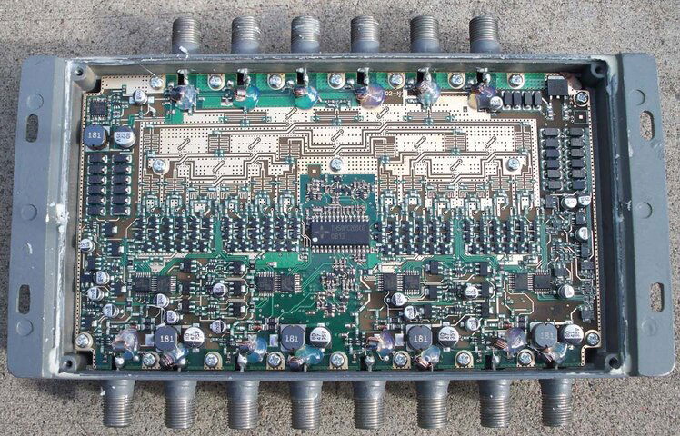
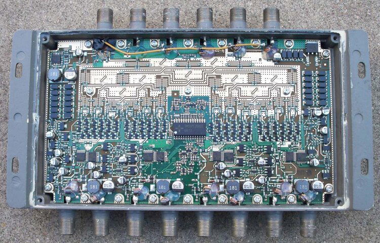
The WB68 innards are pretty easy to access. One peels the sealant off the back, leaving four screws holding on the backplate. With that off, you get to see one side of the circuit board. That's all I needed. Each input has a 16 µH choke used to feed the LNB voltage. I removed the chokes on the Flex Ports for other purposes, and desoldered the choke lead connected to the circuit board for the four inputs I plan to use. These inductors are hot glued to the circuit board, and it seemed reasonable to leave them in that state. I next lifted the center pin of the F-connector for one of the Flex Ports and isolated it from the circuit board with a sliver of electrical tape. Finally I ran a wire from this contact to each of the open sides of the four chokes. The idea was to connect a +18V supply to the rewired Flex Port and have it provide power to each of the four LNBs connected to the WB68.

I wasn't entirely happy about this mod before testing it. There are SMT bypass capacitors in addition to the chokes isolating the IF from the LNB from the WB68's power feeds. Finding capacitors with resonances in or above L-band that could fit this mod wasn't going to be that easy, so I measured the switch performance using the chokes only. On the spectrum analyzer and employing some spot checks with receivers convinced me the caps weren't necessary.

So is this mod worth doing? The alternative would be to use external power inserters, but that's more cabling and parts. I found this took a only a few minutes and was cleaner. For either external or internal power insertion, this takes most of the powering load off the receiver and ensures each LNB gets the optimal voltage for best performance.

For anyone interested, I've attached before and after photos.
 

Attachments

  • WB68 Before.jpg
    WB68 Before.jpg
    222.6 KB · Views: 1,153
  • WB68 After.jpg
    WB68 After.jpg
    203 KB · Views: 1,010
Last edited:
Great job Pendragon thanks for that insight. I really like the fact of decreasing power loading on receivers since I believe this is a significant problem in many receivers.

Looking at the before picture it actually looked to have a possible fault on the centre pin of the 3rd F connector prior to your mod
 
VERY COOL!.....:cool:
I'm all for anything that unloads the regs in these lil riceboxes. They can usually handle 2-3 lnbs w/o issue but for the hard core FTA'er with a multitude of dishes and lnbs they will eventually fail.

Interesting that it covers 250-750 mhz. Is there a system that downconverts to that band? Maybe they going for the UHF OTA band input compatibility. Lots of stations stayed on VHF between 54-88 and 174-216 though.........I dunno.

So.....
"I removed the chokes on the Flex Ports for other purposes...."

....hmmmm. Cant wait to see the next disectable delicacy you have for us. :hungry:

(Another) Great mod PD. Keep 'em coming!
 
Mornin' Cad!

I would think a switching mode (class D) type 19v laptop PS would be a good choice. Compact, lightweight, and lots of current. I pick up every one I see at resale/flea markets etc, if they are less than a buck (usually are)
 
Follow-ups:

1. Looking at the 3rd F-connector, anything weird in the photo is just an illusion.

2. Mel's laptop PS suggestion makes a lot of sense. For testing I had a couple of 1A supplies that have been lying around for a number of years, but they won't be adequate for the switch matrix I'm working on. Instead I decided to pick up some industrial-grade units from Mouser at about $30 for 3.6A. Certainly more expensive than laptop supplies, but they should be easy to package, have great specs, good short/OV protection and should last forever. The Dish bandstacked LNBs are pretty hungry at about 150 ma apiece, so with margin for amplifiers, etc., I should safely cover four 6x8 switches with one supply.

3. DirecTV uses the 250-750 MHz band for LNB outputs, just like 950-1450 and 1650-2150. With all their birds/bands on Ka/Ku, they have a mapping for 12 x 500 MHz per switch, plus the FlexPorts. I'm not aware of a downcoverter for this band; I assume the DirecTV LNBs simply output at those frequencies. There is something called a B-Band Converter (BBC) that will upconvert this to L-band.

4. I scavenged the FlexPort chokes for my junk/spare box, but the first two went into my signal meter, as I had already blown one of the two ports hot-connecting it. Turns out they were using chintzy SMT inductors, and the Zinwells look like they can take some of my abuse.
 
Mornin' Cad!

I would think a switching mode (class D) type 19v laptop PS would be a good choice. Compact, lightweight, and lots of current. I pick up every one I see at resale/flea markets etc, if they are less than a buck (usually are)

Evening Mel!

Great suggestion, I think I have one of those in the junk pile.
 
Now that I think about it, yep, proprietary IRD. :sleeo at that point, I hadn't made it quite to the bottom of the 1st pot of Joe of the day yet.......
They can put their IF(s) anywhere they want. Not a bad idea actually. Been thinking inside the garden variety FTA box design too long......lol


The lil laptop PS's are pretty hard to beat and show up everywhere as surplus these days for pocket change. Lot's potential apps with some 78XX's and modest heatsinking. Most I've seen are 3- 4 A range. Even some of the HP printer class D units are fair at 18/20V @ 1+ A. Other "surplus" PS's used for some HP printers are 24-30 V range, bound to be good for something as well......
How many 6X8's? Ya trying to put your local CATV folks out of biz in your neighborhood?.......lol.


I don't know if you considered it, but maybe feeding each drop thru a current limiter instead of directly might be prudent. A constant direct short somewhere in your array drawing a full 3-4 A might damage other hardware in the path that wasn't the problem. Just a thought.
From what I see, I doubt you'll hurt those chokes with whatever you throw at them. It's a shame that the meter mfgr didnt pony up and use something equal knowing a meter of all things needs to be frequently swapped in and out, generally with the line still powered up. Maybe Zinwell should get into the meter market. :rolleyes:That's a nice looking (read a good quality) PCB, and good pics too! No direct lighting or flash glare. Certainly a good light diffusing setup.


Cad-
Just now catching up. It's been a few days since I posted that 'Mornin' Cad'. You still showed to be on-line when I posted it that morning but I see you RE'd in the afternoon after I disconnected. From what I've seen a few times, this board doesn't operate in 'real time' sometimes.
 
Last edited:
How many 6X8's? Ya trying to put your local CATV folks out of biz in your neighborhood?.......lol.

The switch matrix I'm assembling and tweaking is 44x8. At the moment I've got a mix of the WNC 4x8s and Zinwell 6x8s for a total of 11. Given the performance of the 6x8 switches, I'm planning on using those wherever a LNB will output say above 1600 MHz. But the WNCs are working great below that point, and some will stay for the time being.

I don't know if you considered it, but maybe feeding each drop thru a current limiter instead of directly might be prudent. A constant direct short somewhere in your array drawing a full 3-4 A might damage other hardware in the path that wasn't the problem. Just a thought.

It's something I worried about a little, but I went for the industrial power supplies knowing they'll go into hiccup mode the moment I do something stupid. Not the best solution, but it passed a bench short test through one of the chokes.

From what I see, I doubt you'll hurt those chokes with whatever you throw at them. It's a shame that the meter mfgr didnt pony up and use something equal knowing a meter of all things needs to be frequently swapped in and out, generally with the line still powered up.

My thoughts exactly when I popped the first 6x8 open. I was drooling so bad trying to finish rewiring the switch that I nearly had to get out the heat gun :)

That's a nice looking (read a good quality) PCB, and good pics too! No direct lighting or flash glare. Certainly a good light diffusing setup.

Thanks, I was a professional photographer a long time ago. I still don't own a digital camera, so I have to raid my wife's stash. But I still remember a few things.
 
Pendragon:

Nice mod! I wanted to ask clarifying some things for those less familiar:

- if the switch was designed to pass signals in frequency intervals of 250-750, 950-1450 and 1650-2150 MHz, can it pass frequencies in-between the intervals? Is it generally required for FTA reception?
- What are the advantages to have all LNBFs powered continuously all the time?
- Can and/or should, and how similar mod of the same switch be adapted when using non-bandstacked LNBFs: using both Flex Ports? Or using WNC switch would be a better solution?
- When power to LNBFs is provided by an external PS like in this mod, should LNB (power) option of an STB be switched Off or remain On?
- If you use an external Power Inserted as an alternative to this mod, where on this switch it should be connected to? Using 18V PS in fact is a version of an external Power Inserter, isn't it?
- Could you post a close up photo showing for a single coax port, where exactly you soldered contact to the common wire? Also, do you use another Flex Port, which appears be also powered similar way?
 
- if the switch was designed to pass signals in frequency intervals of 250-750, 950-1450 and 1650-2150 MHz, can it pass frequencies in-between the intervals? Is it generally required for FTA reception?

I tested the switch from 950-2150 MHz and it does indeed pass the 'gap'. I have no use for anything below 950 MHz in my system and I doubt this is of much utility to other FTAers. I didn't measure below 950 MHz, but I would guess it would work fine between 750-950 MHz.

- What are the advantages to have all LNBFs powered continuously all the time?

The main point of the mod for is to provide +18V to all my LNBs. A number of them suffer slight performance degradation when powered by only +13V. The secondary reason is to take the load of powering the LNBs and motors off the receivers.

Based on many years of experience, I expect this will also enhance LNB lifetimes in most cases, and minimize warm up drift particularly at temperature extremes. For example, our DN system as originally installed by them had a DP34 switch that provided constant power to the LNBFs, at least with our receiver mix. Everything worked fine. They upgraded us to a DPP44 switch and every time we tuned to 110W, none of the receivers would lock for the first five minutes. I replaced the 110W LNBF, but it would have been still usable if the DPP44 was supplying constant power.

- Can and/or should, and how similar mod of the same switch be adapted when using non-bandstacked LNBFs: using both Flex Ports? Or using WNC switch would be a better solution?

The Flex Ports require some proprietary DTV commanding to select them. If I had DTV I probably would have scoped it and figured it out, but I don't. Furthermore I have both committed and uncommitted DiSEqC switches in my switch matrix. The Flex Port commanding might not work through these switches, It was convenient to use one of the Flex Ports for power insertion, rather than having to engineer another way of getting the power inside.

Bandstacked LNBs are the most obvious reason to use the extended frequency range of the Zinwell 6x8s, but there are others. Universal Ku LNBFs also extend above 1450 MHz and if you tune some of the Atlantic C-band birds, a number have an extended spectrum that also will result in frequencies above 1450 MHz. If none of the above apply, either the WNC 4x8 or the Zinwell 6x8 should work fine. The Zinwell gives some future-proofing in case you need the full frequency range in the future. However the WNC mod uses the power supply that comes with the switch, rather than requiring an add-on unit. The WNC provides some amplification, which may or may not be appropriate. I use both switch types for their particular advantages.

- When power to LNBFs is provided by an external PS like in this mod, should LNB (power) option of an STB be switched Off or remain On?

You need to leave the STB LNB powering on because it still needs to power the 6x8 switch and select the appropriate input port.

- If you use an external Power Inserted as an alternative to this mod, where on this switch it should be connected to? Using 18V PS in fact is a version of an external Power Inserter, isn't it?

If you use external power inserters, you will need one for each input port. They would be inserted between the LNBs and the switch input ports. I've used them and they were simply clunky. I didn't want to go through the extra wiring of having 44 of of them in between my switches and LNBs, hence this mod. Both the WNC and Zinwell mods I have published are simply internal power inserters instead of external.

- Could you post a close up photo showing for a single coax port, where exactly you soldered contact to the common wire? Also, do you use another Flex Port, which appears be also powered similar way?

Until I mod another switch, the photos I published are all I have. All my modded switches are wired up and in use.

The 6x8 input ports already have a choke coil soldered to them for stock power insertion. I simply unsoldered the other ends of each choke coil from the PCB and this is the point that is attached to the common power bus. I effectively disabled both Flex Ports for reasons explained above. If one figured out how to command them, it would be feasible to extend the mod to power both of these, but the external power would have to come in somewhere else.
 
Thanks a lot! Always useful info in engaging manner. I missed it before. :)

- In some STBs selecting DiSEqC and 22 Khz switch ports are 2 separate setup options for each sat. Should one still leave STB's (separate) LNB power option ON when using this mod?
- What I mean under "using both Flex Ports": connecting 18V PS to one Flex Port and 2 switch ports via a common wire, and 13V PS to another Flex Port and the remaining 2 coax ports of the same switch? Or its impractical? One PS can possibly be connected in parallel to several such switches this way: I assume you do it like this?

When it comes to posting close up PCB photos, I always look for a quality zoom camera, but never managed to locate one around so far. :D
 
Last edited:
- In some STBs selecting DiSEqC and 22 Khz switch ports are 2 separate setup options for each sat. Should one still leave STB's (separate) LNB power option ON when using this mod?

You need to leave LNB power on for this or any switch because they need power for themselves and/or to know which port to select. DiSEqC switches will pass 22 kHz CW tones through to a switch like this.

- What I mean under "using both Flex Ports": connecting 18V PS to one Flex Port and 2 switch ports via a common wire, and 13V PS to another Flex Port and the remaining 2 coax ports of the same switch? Or its impractical? One PS can possibly be connected in parallel to several such switches this way: I assume you do it like this?

If you want to insert both 13 & 18V in this manner, this would be one way to do it. You could also have a single voltage in and use an internal regulator to drop it down to 13V. I'm using 3.6A power supplies to feed four of the 6x8s in parallel. This has been working fine since I wrote the thread.
 
You could also have a single voltage in and use an internal (switch) regulator to drop it down to 13V.
I'd love to see a photo of such mod, since these switches are now sold pretty cheap used in quantities on EBay, while remaining WNCs 4x8 are now a bit more expensive unless one gets lucky (of course not like that feeling lucky pank in "Dirty Harry"). :)
 
I'd love to see a photo of such mod, since these switches are now sold pretty cheap used in quantities on EBay, while remaining WNCs 4x8 are now a bit more expensive unless one gets lucky (of course not like that feeling lucky pank in "Dirty Harry"). :)

I forgot to mention that an unmodded WNC does exactly this. There are separate regulators for each input that feed power inserters. Stock, they alternate between 18 & 13 V . This is one of the nice advantages of the WNC being powered - the receiver supplies virtually no current.

If you want an unmodded WNC, I probably have a few lying around that I am not likely going to ever use, because most of my future needs are in the Zinwell 6x8 direction. PM me if that would help solve your search.
 
I found Pendragon's earlier thread on the WNC SWA-48 switch so compelling, that I went out and got myself a couple.
Naughty Mods II: 4x8 Switch with All 18V outputs
For its intended purpose, whether it supports frequencies all the way out to 2100mhz without roll off, is totally irrelevant.
I wouldn't use bandstacked LNBs with such a switch, anyway.

See comments in the above thread for where I located good deals.
 
Anole

Something definitely happen to you. I know, steroids are raising in popularity: do you want to catch up in stature with some known Kalifornian? :D
 
The Flex Ports require some proprietary DTV commanding to select them. If I had DTV I probably would have scoped it and figured it out, but I don't. Furthermore I have both committed and uncommitted DiSEqC switches in my switch matrix. The Flex Port commanding might not work through these switches.
Could you conclude from the switch schematics, if switching to a Flex Port is done by a variation of DiSEqC command, or by hardware means. I.e., signal from one Flex port may be frequency shifted and diplexed with signal from 2 regular ports (say those requiring 22 KHz signal to switch to) using the same internal matrix as Zinwell 4x8 switch. Once received by an STB, it can be separated and converted back. Did you have an impression that Ka-to-Ku converter like SUP-2400 is integrated into this switch to work only with Flex ports? It would be nice to try decipher required code to switch to these extra ports, which can be quite useful with a Sat PC Tuner. I contacted Zinwell about required command sequence to no avail so far. How would you try to scope these commands? ;)
 
Could you conclude from the switch schematics, if switching to a Flex Port is done by a variation of DiSEqC command, or by hardware means. I.e., signal from one Flex port may be frequency shifted and diplexed with signal from 2 regular ports (say those requiring 22 KHz signal to switch to) using the same internal matrix as Zinwell 4x8 switch. Once received by an STB, it can be separated and converted back. Did you have an impression that Ka-to-Ku converter like SUP-2400 is integrated into this switch to work only with Flex ports? It would be nice to try decipher required code to switch to these extra ports, which can be quite useful with a Sat PC Tuner. I contacted Zinwell about required command sequence to no avail so far. How would you try to scope these commands? ;)

I'm only working from memory and I've never had any interest in DTV, but I believe at least the primary four ports are intended to pass 3 x 500 MHz bands each (250-750, 950-1450, 1650-2150). The flex ports may be capable of doing that as well, but I don't have a satellite mapping handy at the moment. I've seen them on the web.

I don't have a schematic of the 6x8 and I have no motivation to trace the prints to determine if this would reveal anything. That doesn't sound very interesting. If I had access to a DTV receiver commanding this switch, it would be child's play to figure out what the commands are, and whether they are simple bursts, DiSEqC or variations, or whatever. PC tuners often have a myriad of commanding possibilities beyond spec DiSEqC, so there's always a decent chance one could be taught to switch these ports.

I'm kind of surprised no one seems to have reverse engineered this or leaked the spec. I'd do it but I'm not shelling out for a DTV setup, which seems the quickest route. Perhaps some of the other mad scientists here with sufficient equipment access would be game.
 
Since WB68 switches are intended to work with low current LNBFs, these Flex ports may be always powered, hence no commands beyond regular 4x8 switch scope would be required if signal combining (with or without freq conversion - bandstacking) is involved. Such combining, if present, would probably produce the intended by Zinwell result only if the Flex port is connected to a proper freq (Ka?) DTV LNBF, hence it may not work correctly with a bandstacked Sadoun's LNBF. Even in that case it MAY be possible to separate (converted) signal at each OUT port of the WB68 switch using a modded diplexer or high freq splitter, with added Freq Converter to one leg of it if needed, and pass it via an unused port of an 8x1 switch to an FTA Receiver to use these extra Flex ports. Of course, some signal degradation may result from the extra gear, but in-line amps will presumably compensate this. Or, may be merely editing Channel List file freqs matrix will do. Of course its just all guessing without Zinwell docs.

Regarding your concern that a DiSEqC switch may block these DTV Flex Port commands (if any), are regular DiSEqC 4x1 switches cascadable, i.e. can they pass full scope of DiSEqC commands? It sounds, they don't, only 8x1's can. I still wonder, if there is any measurable incoming signal on a WB68 Out port when 18V and 0/22 KHz is supplied to it, if only the switch's single Flex port is connected to a signal source - that would clarify if extra commands are used by a DTV STB to switch to a Flex port or power it up. ;)
 
Last edited:
Status
Please reply by conversation.
***

Users Who Are Viewing This Thread (Total: 1, Members: 0, Guests: 1)

Who Read This Thread (Total Members: 4)