

Social Feed
Can I run 2 hoppers on a Home adapter(plug-to-internet)?
One Hopper hard wired to duo-port,the other via wireless network?
I have a 4 port wireless router with 2 spare ports,so can I simply plug it into a wall-plug adapter and then into the second Hopper from other adapter?
If so,will I still have separate,individual tuner and DVR ability from each hopper?
Is there a simpler way to accomplish this without another coax from hopper to DuoPort?
Thanks in advance for all of your help.
20 Replies
·
1664 views


Staff member
HERE TO HELP YOU!
Cutting Edge
Sometimes a thread gets so many posts in it that is can cause issues for the server so that why today we introduce The Song Name Game Part 3!
So let the game continue!
The last song was added by Bobby who posted...
One Meat Ball - Andrews Sisters
CONTINUE ON AND HAVE FUN! WELCOME HOME TO SATELLITEGUYS.US!
Here are the original rules for the game as posted by WebbyDude back in 2006. http://www.satelliteguys.us/threads/68645-Song-Name-Game
Just name a song title and the band who performed it. The next person does the same thing, but needs to list a song title or band name which includes a word from the previous entry. Pick songs from any genre.
Example:
Long Live Rock and Roll -- Rainbow
Rainbow in the Dark -- Dio
Another example:
Ride the Lightning -- Metallica
Lightning Strikes -- Ozzy Osbourne
Get it?
An additional note: we all know that song titles, sometimes, use profane words. Because this is a family friendly website it is advised that you clean up that title up a bit. This is accomplished by using something like sh!t instead of the real word. Thanks....
68537 Replies
·
2673549 views


Lifetime Supporter
Schedule drops tomorrow. Mandatory mini camps in June. Hall of Fame game August 6th.
116 Replies
·
1829 views





Supporting Founder
Lifetime Supporter
No idea what improvements might be involved.
24 Replies
·
1063 views


iJustine
Time for another AWESOME video from iJustine!
View: https://www.youtube.com/shorts/P4_TzYKwcNY
Direct YouTube Link - This is iPhone Duo!
The official iJustine Website's Website
Buy her book!
View: https://www.youtube.com/shorts/P4_TzYKwcNY
Direct YouTube Link - This is iPhone Duo!
The official iJustine Website's Website
Buy her book!
0 Replies
·
10 views
TWiT Tech Podcast Network
Time for another AWESOME video from the TWIT Network!
View: https://www.youtube.com/shorts/-O2iLThF4z8
Direct YouTube Link - Generative AI: Revolutionizing Game NPC Dialogue & Behavior? #shorts
TWIT's Website
TWIT Live Feed
View: https://www.youtube.com/shorts/-O2iLThF4z8
Direct YouTube Link - Generative AI: Revolutionizing Game NPC Dialogue & Behavior? #shorts
TWIT's Website
TWIT Live Feed
0 Replies
·
8 views

Staff member
HERE TO HELP YOU!
7 Replies
·
102 views

Staff member
HERE TO HELP YOU!
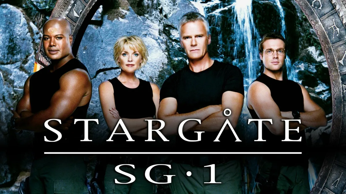
Stargate SG-1 cancelled, Atlantis renewed

Monday - August 21, 2006 | by Darren Sumner
The future of Stargate is in question today, as SCI FI Channel has cancelled the long-running Stargate SG-1, Multichannel News reported today and a GateWorld source has confirmed. The news regrettably follows the airing of the show's milestone two-hundredth episode on Friday.
Stargate Atlantis, meanwhile, has been renewed for a fourth season, with the network hoping to see that the spin-off series can stand alone, according to a source.
Source Gateworld
2033 Replies
·
184138 views


TWiT Tech Podcast Network
Time for another AWESOME video from the TWIT Network!
View: https://www.youtube.com/shorts/wVdnjWsw2Uk
Direct YouTube Link - Defender on Linux: Microsoft's Big Security Move #shorts
TWIT's Website
TWIT Live Feed
View: https://www.youtube.com/shorts/wVdnjWsw2Uk
Direct YouTube Link - Defender on Linux: Microsoft's Big Security Move #shorts
TWIT's Website
TWIT Live Feed
0 Replies
·
15 views

Supporting Founder
Really excited for this season with Kentucky having a new coach and some really exciting recruits. Probably won't last long, but here's hoping this season is great.
152 Replies
·
1932 views
 . Hated to see my dawgs go down but I still say being ranked #1 is a hex on you!

TWiT Tech Podcast Network
Time for another AWESOME video from the TWIT Network!
View: https://www.youtube.com/shorts/PSGt6dUXdnI
Direct YouTube Link - RTX Spark: NVIDIA's AI PC Powerhouse Details! #shorts
TWIT's Website
TWIT Live Feed
View: https://www.youtube.com/shorts/PSGt6dUXdnI
Direct YouTube Link - RTX Spark: NVIDIA's AI PC Powerhouse Details! #shorts
TWIT's Website
TWIT Live Feed
0 Replies
·
21 views