Antenna Grounding...

  • WELCOME TO THE NEW SERVER!

    If you are seeing this you are on our new server WELCOME HOME!

    While the new server is online Scott is still working on the backend including the cachine. But the site is usable while the work is being completes!

    Thank you for your patience and again WELCOME HOME!

    CLICK THE X IN THE TOP RIGHT CORNER OF THE BOX TO DISMISS THIS MESSAGE
Status
Not open for further replies.

dejelo

New Member
Original poster
Mar 30, 2008
4
0
I wanted to ask this question in the "Installer's Forum", but I'm not allowed "in" - Have to be an "installer"! Don't see any other good place for question of this type...:confused:

My question has to do with antenna grounding... my antennas [TV - DirecTV Dish - Satellite Internet Dish] are mounted on side of house, above porch roof... without grounding at present.

Is there a standard way to mount a grounding wire/cable across a porch roof, then down to ground level? Hate to install cable brackets by making holes in roof shingles for this... and don't see easy way to route cable through the roof, then through porch deck - but, seems like that kind of "straight run" would be the ideal "run" for lightning protection.

Is there some standard method for doing this - or do I need to find an "inventor"?

If no one here can answer... where else should I go to "ask"?

Thanks in advance.
 
Legal advice- Follow the NEC and local building codes.

now that that is over with, If I had your situation I would run an aluminum solid wire I bought at Home Depot that they sell for antenna grounding from the base of the dish mount that is bolted to the wall by the shortest distance over the porch roof and straight down the wall to an 8 foot ground rod driven into the ground next to the house and side of the porch. Home Depot sells these too. I would never go through the roof. That would violate the code. I would fix the aluminum wire to the wall with staples or standoffs.
 
Don, thanks for responding...

If I may... ask you to expand a little on this...

1. Isn't there a problem with the "turns" in routing of the wire?... across the roof, then around the gutter and back under the eaves [about 150 deg. bend]... then [a 90 deg. bend] down a post to the ground. I've always heard it said that lightning won't make those turns.

2. Is there another reason for "grounding" - such as static discharge - that makes grounding necessary, whether lightning will make those turns, or not? I've noticed no problems that make me think: "Aha! - Static! - I need to fix that!"... but, maybe it isn't that obvious?

Not that I'm reluctant to "do this"... I'd just like to take care of the details properly.

Thanks again, for your time on this.
 
1. Well now you're going into a completely different debate.

First of all the only issue one has with static electricity conduction is corona point leakage which would act as an attractor. Those would be very sharp bends that would build a charge. But this is a real stretch in reality and personally this is not something to worry over

The case for grounding of any antenna is NOT to properly conduct a billion megawatt lightning strike direct hit safely to ground. Face it if you get such a hit, you're toast, no two ways about it as no little old 6 ga wire and an 8 ft ground rod will protect your ass from the smack of GOD. :)

What grounding is all about is to continuously bleed off static electricity in small amouts to prevent it building up on the dish itself as would be the case from an ungrounded dish or one that was grounded only with a convoluted path through the coax shield to the receiver case to the electrical outlet to your panel box to the ground wire on it.
If with a good outside simple path to ground, your Dish or other antenna will remain low on static buildup and will be less likely to attract that direct hit in the first place. Few people seem capable of understanding this but this is the real purpose of grounding, yet I get asked the question of direct hits all the time. Again, if you take a direct hit, consider you're toast with or without the little ground rod whether otr not it has one or two or no bends in the wire.

2. Answered above.


There is indeed a third reason to ground your antennas properly as defined in the NEC and local building codes if you still don't want to accept the science. It is a legal issue. If you have a home that is in violation of building codes and National Electric Codes, you risk rendering your Home Owner's insurance for damage due to lightning strikes null and void. In some parts of the country, Insurance companies are now doing code inspections and if you are in violation, your will get a citation from the insurance company requiring you to fix the violation. Your insurance will not cover you even though you paid the premium until the code violations are corrected.


In summary-
Reason #1- Keeps static buildup from damaging your receiver

Reason #2- Reduces your risk of direct hit by lowering the attraction to lightning by keeping the static electricity drained off.

Reason #3 It's legally required.


Grounding to route direct hit to ground to avoid catastrophic damage is a myth.
 
Each antenna is required to be grounded, also each coax must also be grounded. Pictures of your outside setup would be helpful.
 
I agree with the 8' ground rod at the closest point, but that also has to be bonded to your electrical entrance. If your entrance is close to where the ground wire would come over the roof, just bond to that. Not being bonded to the entrance is also a code issue (IIRC - I'm not a licensed electrician) and risks creating "ground loops" that could cause other performance issues with your electronic equipment in the same "circuit".

The issue with bends, etc. is a problem with inductance. Bends and conductor geometry are contributors to higher inductance that is an impediment to grounding high-speed events like a nearby strike. In general you want short straight runs, and the best conductors are broad and flat vs. circular in cross-section, not practical for a residential installation. As Don mentioned, no practical residential grounding scheme will protect you from a direct strike. Grounding will however do a great job bleeding-off static, and might give you adequate protection from the induced EMF of a nearby strike, which is much more likely statistically.

I ran #10 THHN (stranded, insulated copper) wire from my dishes to the ground block, then on to the electrical entrance. For my OTA antenna I ran #6 copper (standard household "ground" wire) all the way from the top of the antenna itself, through several bonding clamps, through a 4' ground rod at the antenna base, through the grounding block, then on to the entrance. For both the "real" ground is the one at the entrance. Copper is more expensive than aluminum but the superior conductor. If you're using aluminum, make sure you use a proper anti-corrosive grease anywhere you are connecting to copper, like ground terminals. Doesn't hurt to use that at every connection...
 
OK!!:up - Don... Van - (please don't shoot the penguin!)... & bhelms....

I feel like I've hit the Jackpot! That is exactly the information I was trying to find! I was suspicious myself, about the effort to "stop" a direct lightning strike - but had never heard the other details about the "theories & reasons" for grounding wires.

Also, the specifics on ground runs back to the "electrical entrance" is something totally new to me - did not have a clue about that! [I got some "radio electronics" training in the military - then went into another line of work - I do remember most of the Morris Code! - but that's no help here.]

"Grounding" now looks like as big a project as the original antenna installations.

Woe is me! But I really do appreciate all the help. Thanks again!

What a great web site!! I'll be talkin' this up in my Round-Table-Gang on the weekends. Take care...
 
bhelms- There are some flaws in your grounding procedure-

The concept of using copper and stranded wire, as well as the theory of inductance. Please understand that we're dealing with a different type of electricity here. We're dealing with static electricity that has quite different properties than RF (this is where stranded wire is important) and low frequency house current (where ground loops and inductance become factors.
With static electricity, you try to create a circuit that continually bleeds off static buildup which is the primary lightening attactor. Low static build-up = safe. The problem with sharp bends is that a sharp bend is a place where static electricity will slow down and take a rest in it's journey to the earth ground. The static is created by wind blowing past a collector which can be anything, including trees and plastic fencing and metal like antennas. The more points in the geometry of the static collector the better storage it has and the greater it attracts lightening. If you have sharp points as necessary like a tree or a, antenna design, the best you can do is bleed off that static buildup as quickly as possible by the shortest and best path to earth ground. Static electricity can be slowed down by a conductor with high surface area (stranded wire) and corona points (sharp bends).
Now about copper vs. aluminum for static grounds- Years ago late 1800's and early 1900's the theory was in practice but observers often discovered the opposite was true and that was lightening rods and conductors outside made of copper and brass would fail and actually become more prone to lightning strikes. The cause was the rapid buildup of oxidation which was a material that easily stored static electricity (bad) Aluminum solid wire, was far less prone to oxidation and was a much better lasting static electricity conductor. If you use copper wire it will work fine until the shiny luster is gone, then change it. It becomes a dangerous attractor once the oxidation turns green! However, this copper wire corroded green will still work well as a low frequency conductor for power.

The bonding issue is an interesting one as I have seen this vary with building codes in different communities. It is usually specified as to the distance between the meter box ground and the antenna ground location. If it is over a certain distance, you are not required to bond the two with a horizontal conductor at ground level. Best check with local building codes for this requirement. By shortest path, mine would be a wire nearly a hundred feet.

Personally, I have an interesting arrangement. I have 3 dishes. Two are 6 ft apart and the third is about 14 ft away. I have switches located separate from the dishes. One for DirecTV and another for DishNetwork. Two of the dishes are grounded to a 10 ft rod using solid copper number #6 coated with weather proof clear Krylon. Thise are vertical conductors about 10 ft long from ground to dish and switches. I also have a ground block for each RG6 just before it enters the house block wall about 12 inches above ground rod. Next I have a VHF/UHF LP yagi antenna that is on a 10 ft mast in the center of the roof. I run a #6 Aluminum solid wire down from the antenna along the mast bonding it to the antenna boom and at the mast base above the house roof. The mast is mounted pipe strap fashion to a cast iron sewer pipe vent. The aluminum wire then runs down the side of the house along side of the other dish and switches grounds to it's rod. The two rods are horizontally bonded. about 14 ft away I have a third ground rod below my third dish. It is not horizontally bonded as it is 14 ft. away. The electric meter is on the other side of the house and is about a 100 ft. run around the perimeter distance.
 
Don - The 10 ga. copper wire I used in my sat. dish grounding is more than adequate per common dish grounding recommendations for static dissipation. Please see the link below from one of our site sponsors, Sadoun:

Grounding your satellite dish and system

Indeed, in many dish installations the only ground from the dish itself to the coax grounding block is the simple "messenger wire" (18 ga.?) paired with the coax. Then from the ground block to the entrance ground point the conductor is to be 10 ga. copper or 8 ga. aluminum.

Note also the requirement for the 6 ga. or heavier bond from any ground rod to the entrance panel, the "central building ground". Failure to provide this bond can cause severe equipment damage via EMP-induced currents in the aforementioned ground loop. (I also alluded to the more common ground loop problems many folks encounter, which in my case was continuous "noise".)

In my case the choice of stranded THHN was one of convenience as I had that type in abundance. I soldered an "eyeloop" on the dish end, slipped it over one of the dish mounting studs, and applied a liberal amount of the a/m anti-corrosive grease before tigntening down the nut on it. I don't think there will be any corrosion problems there. I also used that grease at the grounding block, there primarily because of the dissimilar metals which it is designed to protect.

Stranded vs. solid for static? I contend that altho' dissipation is a "continuous event", it is happening in discrete "quanta" of charge vs. a continuous current. The static build-up, from reasons you described and others, and propagation are rapid and sporadic. Thus the "frequency" of discharge events is high and the charge subject to the "skin effect" of all conductors carrying high frequency energy. So in that case the stranded wire would have a lower impedance to the flow. Which of us is right? I queried some folks about stranded vs. solid and no one could voice a real objection to the stranded wire in this particular application so I went with it. If I had it to do over I would probably use solid. Tho' harder to work with, it will probably be a bit cheaper.

Another thought - in substantial grounds designed for true lightning protection, like antenna towers, the conductors are usually broad and thin for low inductance, as I mentioned. That also has the effect of greatly increasing the surface to volume ratio of the conductor, which would seem to be contrary to your explanation (?)

Re: my OTA system, agreed that copper will corrode, that's why I used the anti-corrosive grease at all the contact points. That 6 ga. solid copper wire is a near straight run from the antenna itself to the ground rod, with a wide 1/2 loop at the rotation point and a slight curve coming off the mast to the close ground rod. From there the unbroken wire makes a sharp turn (unavoidable) to the ground block, then as straight a run as possible to the entrance panel. The outside of the exposed wire is indeed dark from corrosion but I don't see that as a problem. It's the connection points that matter and I believe I have them well protected. Do you see any problem with the system as now more fully described...?
 
Last edited:
I recently moved my TV antenna (10 ft) from the attic to the roof by the chimney to create some space to install an Airscape whole house fan and to get few more channels. Then I realized that I created more work for myself as far as installing proper grounding for the antenna goes. Thinking of safety I wanted to do it right. I live in a U shape condominium building in an upstairs unit at the inside tail-end of the U. Our electric meters for all units are at the very front where all the grounding is done I'd imagine. So, practically it will be really difficult to connect the antenna grounding wire to the grounding cable that is connected to the electrical meter.

I'll ask few questions. Please forgive me if I'm bringing up something that has already been adressed although I'll try not to. Overall I'll ask your guidance as I understand that you have experience in this subject.

I've been doing some research for few days. I installed the antenna 4 days ago and did not connect the wires yet as I wasn't sure of the proper grounding process. I stumbled upson this thread today and found pretty good information. Thank you all.

I wanted to clarify few things. If I were to use an 8 AWG copper grounding wire do I connect it to to the antenna mast and then run it through the coax grounding block by the fascia (with drip loops) without cutting it and then run it straight to the grounding rod? Or do I need to run a second wire from the coax grounding block to the grounding rod? I've already purchased the grounding rod and the clamp. I'll probably buy the copper wire tomorrow after doing a measurement from the roof again. Since it is kind of expensive I wanted to waste the least I can.

Now just like dejelo before I can't go straight towards the ground from the chimney, I have a patio roof to cover. At the same time I installed the antenna at a corner of the chimney so that less of the antenna material hangs on top of the metal chimney cover. What that means is I have to take 2 turns and stop at a fascia board where I'll install the coax grounding block and then from there cross the patio roof area which is at least 10' below and turn towards the ground by the gutter. Possibly a picture would be good. I'll try to post one as soon as possible. I didn't see a 8 AWG grounding wire at Home Depot or Lowes that is insulated. My other question is will I create a dangerous situation by routing the ground wire touching the metal gutter?

I'll wait for the replies.

Kind regards,
 
Last edited:
Per NEC, antennas can be grounded using #17 Copper Clad Steel, #10 copper, or #8 aluminum. There is no distance limitation on antenna ground wires, only ground wires for coax cables do. Generally, NEC doesn't permit the practice of grounding multiple systems on the same ground wire such as a #10. However, its an industry-wide practice to run the antenna ground to the ground block and piggy back on to the coax ground wire. Your best bet is to run your conductor direct to the ground rod for the house electric or the main ground wire using a split bolt or bonding to the meter pan, etc. As far as running the ground wire, you can attach it to the roof using some liquid nails if you don't want to penetrate the roof. Bends in the ground wire should be smooth. Think of a surge as an 18-wheeler moving very fast. What's gonna happen to the truck if it makes a right turn while doing 50mph? In this case you can't control the size or speed of the truck, you can only make the turn a smooth bend.
 
[I got some "radio electronics" training in the military - then went into another line of work - I do remember most of the Morris Code! - but that's no help here.]=.


I hope you remember the codes better than the name of the codes... it's Morse Code. ;)
 
vegassatellite- I liked that truck analogy. I'll have to remember that. :)


NEC doesn't permit the practice of grounding multiple systems on the same ground wire such as a #10. However, its an industry-wide practice to run the antenna ground to the ground block and piggy back on to the coax ground wire.
It's been quite awhile since I looked at the code on this but I wasn't aware that the NEC did NOT permit the industry standard. I have my system antennas and dishes all grounded with the #8 Aluminum to their own 10 ft rods. Then I have the switches and coax blocks piggybacked with #10 copper to its own rod. The farm has a switch for D* and one for E* and then there are 9 RG6 coaxes that run into the house. The distances between the two switches is about a foot and then 10 ft to the coax blocks about 1 ft to the ground rod. It would seem pretty impractical as well as way overkill to have each of those on their own ground wire / rod. I thought it was overkill to have a rod for each of three dishes but that is what I did.
 
Can I add a question here please on Ground Loops and Lightening?

My dish is on the oposite side of the house from the electrical ground due to line of sight issues. This dish is on the 1st story level roof on the side but not on the 2nd story roof.

It is grounded on that side of the house to a 8' ground rod that is NOT BOUNDED to the other side of the house main ground. I know now this against code, but the electrician that put the rod in did not do anything to bound it (I watched him do it).

I was reading on some other sites that not having it Bounded to the main will cause MORE if a risk form lightening. I ask because a month ago Lightening hit down the street and I took some surge damage, mainly through the Catv Telephone line and internet but it also took out the garage door opener and my DIsh Multi Switch.

What should I do?

Option One- Leave it as is (ground on other side to an 8' ground rod and Not bounded to the rest of the house

Option Two- or buy a very long wire and bound it to the main electrical ground? We are talking a 27' run.

Option Three- un ground the dish as ground loops cause more issues as in my Surge issue from last month?
 
The danger with a separate ground rod for the satellite system is if the path to that ground rod is lower resistance than the path to the house electrical ground, then dangerous voltage from the house electric can potentially be routed through the satellite system to its ground.

You're better off to disconnect the isolated ground than to leave it connected if you aren't going to back bond it.
 
But if you can effect the bond with a 27' run without too much hassle, that's the better option, and it would meet code. I'd go with #6 solid copper for that run. Actually 27' is not all that far! My (#8) bonds for the pool are more like 60'...
 
Question. Can you ground to a Hot Tub Electrical Box?

I went out and re measured (I was way off).

It is 57 feet to the Main Ground. about 67 if you count the Dish on the 1st story roof line.

It is about 25' to an Out Side Hot Tub Electrical Box with 220 service in it. The box is out side mounted on the house.

Can I ground to it? If so how do you connect to it?
I would not need a 2nd ground rod bounded to the main as it is closer.

I'm no expert on NEC but I believe you can ground to the conduit on the line side (not the load side) of the service disconnect for the hot tub. You can use a pipe clamp or a small 6" ground strap.

Also, NEC doesn't specify any limitations on the length of the ground wire between two ground rods, only that it must be #6 copper or larger.
 
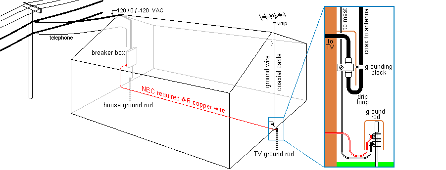
Ran across this image and text in my travels. Not sure of the source.

The NEC requirement

The National Electrical Codes (document NFPA 70) requires another wire be added to the grounding described above.

This 6-gauge wire, shown in red, connects the new ground rod to the breaker box (typically). This wire will help absorb the lower frequency components of a direct strike. If this seems like too much work for too little benefit, don’t be discouraged from at least installing the ground rod. But if your antenna is situated where a direct strike is likely then installing this wire is strongly advised. The wire should run close to the ground so that side flashes will likely arc to the ground. It is OK to run this wire around the exterior of the building. In this case keeping the wire 6” to 12” above ground is best. The length of this wire is less important, but turns should still be curves of large radius.
 

Attachments

  • grounding.gif
    grounding.gif
    11.5 KB · Views: 2,483
One thing that wasn't mentioned is if you have a deep water well on your property, as many of us who live in the country do. If your outside BUD takes a hit and you have it grounded to a ground rod that hit is going down your well. That well casing is the largest, deepest grounding rod on the property. Ask me how I know. When mine took a hit the only damage to the system was to the Videocipher cartridge but the well pump was toast. Make sure your well circuit is properly protected to prevent backfeed into the house (GFI). Here's some reading from "Specifications for Lightning Protection — ASAE Engineering Practice." These are designed for farms and are not specifically laws but give a good insight into what's really involved, such as taking into consideration the type of ground and it's ability to disipate current. Much of what you read here has been incorporated into local codes so you may want to check with your local municipality.


"Grounding
Proper grounds are critical to assure dissipation of a lightning
discharge without damage. Extent of grounding will depend on the
character of the soil, ranging from two simple 10 foot grounds for
a small building located on deep conductive soil, to an elaborate
network of cables and rods or plates buried in soil that is dry or
rocky and of poor conductivity.
Minimum acceptable standard for each ground electrode shall be a
copper-clad steel rod at least 1/2 inch in diameter and 10 feet long.
Rods of solid copper 1/2 inch in diameter may be used in lieu of
copper-clad steel. Stainless steel ground rods are also acceptable
where acid soil conditions exist or other conditions warrant
substitution of stainless steel.
Wherever practicable, connections to ground electrodes shall be
made at points not less than one foot below grade and two feet out
from the foundation. Grounds shall be distributed and placed at
corners and other locations in a manner to direct the flow of
current out from the building rather than under it. Placing of
grounding under a building (as in extending a building) shall be
kept at a minimum. There shall be a ground at each down
conductor.
In moist clay, the ground shall extend vertically not less than 10
feet into the earth, and the earth shall be tamped along the full
length of the ground.
In shallow top soil where bedrock is near the surface, the lightning
conductor (extensions of the down conductors) shall be laid in
trenches extending away from the building. Trenches shall be at
least 12 feet long and one foot deep in clay soil, and at least 24 feet
long and 2 feet deep in sandy or gravelly soil.
In moist sandy or gravelly soil of ordinary soil depth, 2 electrodes
shall be driven at least 10 feet deep at each ground. The conductor
shall be extended out from the building in a trench at least 2 feet
from the wall. The two electrodes shall not be spaced more than 6
feet apart.
All underground metallic piping, including water piping, well
casings, sewer and septic lines, shall be connected to the grounding system with main size conductors and special fittings with a minimum contact surface to the pipe 1.5 inches long and 2 square inches area. Water pipe, well casings, sewer and septic line
connections are in addition to the required number of regular
grounds. If a metal water pipe, well casing, sewer or septic line
enters a building, at least one down conductor of the lightning
protection system shall be connected to it.
Lightning Arresters
Radio and television masts of metal, regardless of location on a
building, shall be bonded to the main conductor of the lightning
protection system with a main-size conductor and acceptable
fittings.
To protect radio or TV equipment against surges, a lightning
arrester shall be installed on the lead-in wire, tape or cable and
bonded to the lightning protection system directly or through a
common ground. Secondary service arresters shall be installed by
the lightning protection contractor, electrical contractor or the
electric utility company. Such arresters shall be installed on both
overhead and underground services at the electric service entrance,
or at the interior service entrance box, depending on local
regulations. Before installing a secondary service arrester, it should
be determined that the neutral wire is adequately grounded,
preferably to a metal water pipe system that enters the ground."
 
Status
Not open for further replies.

Users Who Are Viewing This Thread (Total: 0, Members: 0, Guests: 0)

Who Read This Thread (Total Members: 1)