Channelmaster 1.2M C/Ku Feed

  • WELCOME TO THE NEW SERVER!

    If you are seeing this you are on our new server WELCOME HOME!

    While the new server is online Scott is still working on the backend including the cachine. But the site is usable while the work is being completes!

    Thank you for your patience and again WELCOME HOME!

    CLICK THE X IN THE TOP RIGHT CORNER OF THE BOX TO DISMISS THIS MESSAGE
Status
Please reply by conversation.

caddata

SatelliteGuys Pro
Original poster
Jun 8, 2005
333
1
Jacksonville, FL
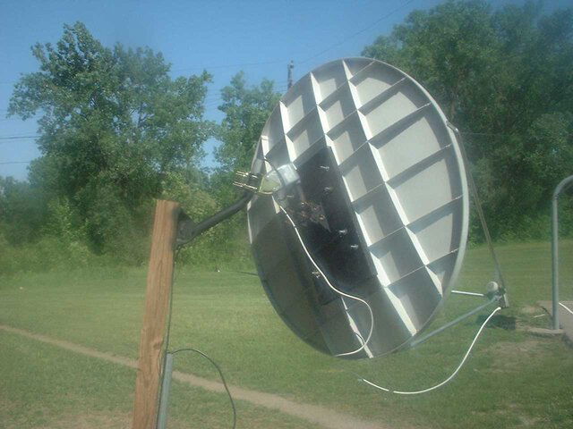
Attached is an image of a standard Channelmaster 1.2M Ku feed with the BSC621-2 superimposed over it. Does this look like it makes sence?

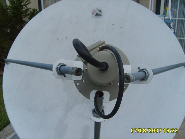
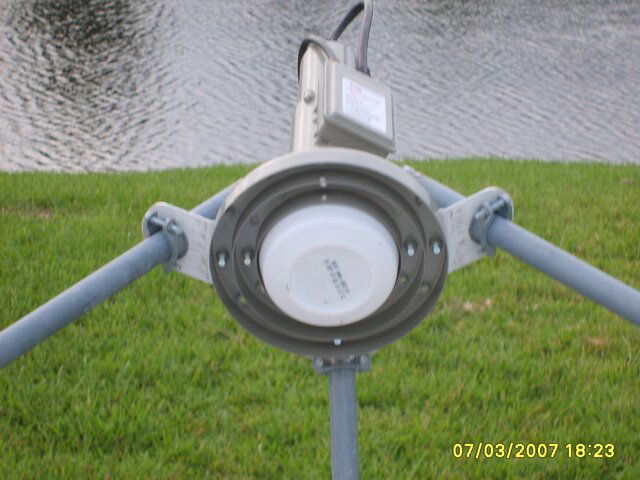
I think that the flat scaler will work, although I know some of you have used the "coned" scaler. The "signal cone" appears to require the BSC621-2 to be about 1/4" closer to the dish than the original Ku feed.

I know that some of the adaptions have moved the C/Ku feed further away from the dish. If my layout and dimensions are correct, it appears that those adaptions have placed the C/Ku feed on the far side of the focal point convergance. The signal actually makes an "X' at the focal point and widens as it passes further from the dish. Just as light does as it passes thru a lense.

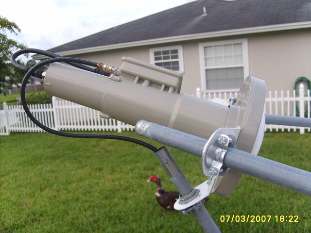
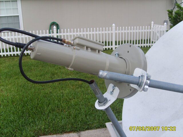
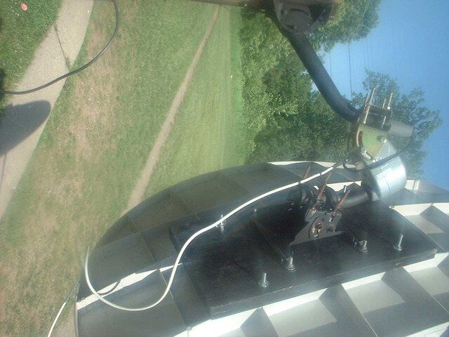
I'll fabricate a new bracket from aluminum that will replace the original plastic one. The new bracket will relocate the support legs to clear the new scaler, while at the same time allow adjustment closer to and away from the dish on the same angle as the original feed.

Please post your comments and let's kick this thing around.

Harold
 

Attachments

  • Channelmaster_feed01.bmp
    861.4 KB · Views: 658
great drawing , glad someone else has got an intrest. i can only guess at the results but i'm working on a project thats close to this.

I will be using a 1.0 meter primestar dish. I suspect that on these offset dishes the beam is pinpointed like you have shown in the drawing. but and i'm really out here when i say this cause i have nothing to support it. is that the focal point is different and really can't be marked with the scaler ( hence the conical scaler). i also believe its further back than you have shown.. although the probe for c band is shown further back than the focal point is shown in the drawing. Thus making the ku probe fall short of the Focal point. now all this is guessing and i will probably be the only one with this opinion.

but great work . now if i could only fab one of those conical scalers
or find out if your extension will work

and good luck with your testing i can't wait to hear your results
 
...focal point is different ...

I've seen this idea of the focal point of the Ku being different from the C, and I can't bring myself to believe it because microwave behave exactly as lightwaves.

A mirror doesn't know what color of light it reflects, just as the dish doesn't know the frequency of the waves (light, sound, or electromagnetic) it's reflecting. Everything that hits the surface of a dish gets reflected to the same focal point. Lightwaves, soundwaves, and electromagnetic microwaves are all at the same focal point. Have you ever been working near the focal point of a dish and heard the "sounds of nature" (birds, wind, leaves rustling)? My first encounter fascinated me. The dish had been rotated all the way to the West and was about 6 feet off the ground. I stopped working and turned my good ear to the focal point and was suprised at the things I could hear.

Once the feedhorn is located at the proper focal point, the focused signal (containing both C and Ku waves) enter the C band resonate cavity. The focused signal is like an onion with higher frequencies at the center in a ball, layered outside are lower frequencies in progessively larger balls all with the same centerpoint. C band waves find the C band probe inside the first resonate cavity. As the rest of the collected signal passes into the Ku band resonate cavity Ku microwaves find the Ku probe and resonate to it.

Harold
 
i would like to know your compleate setup ... dish motor ect...
i am trying a simular project ...i also have the channel master 1.2 meter dish
but i am going with a different lnb .. a geosat c/ku lnb
 
i would like to know your compleate setup ... ...

This Channelmaster project will replace my current .9M Fortec that uses Sadoun's old trademarked actuator.

I'm not sure what motor I'll use on the Channelmaster, although I had kicked around the idea of fabricating a polar mount that would use an 18" linear actuator driven by an analog Uniden Supra IRD. That part of the project is in the distant future after I've worked out the feed.

Harold
 
i am going to have an hh120 that i plan to use with my dish..it should be good enough to motor it around the belt....my current motor was working a little but decided to go to far east and stay there
 

Attachments

  • john1.jpg
    john1.jpg
    76.7 KB · Views: 458
  • DSCF0094.jpg
    DSCF0094.jpg
    87.6 KB · Views: 390
  • DSCF0093.JPG
    DSCF0093.JPG
    160.1 KB · Views: 478
  • DSCF0092.JPG
    DSCF0092.JPG
    161.8 KB · Views: 438
Once the feedhorn is located at the proper focal point, the focused signal (containing both C and Ku waves) enter the C band resonate cavity. The focused signal is like an onion with higher frequencies at the center in a ball, layered outside are lower frequencies in progessively larger balls all with the same centerpoint. C band waves find the C band probe inside the first resonate cavity. As the rest of the collected signal passes into the Ku band resonate cavity Ku microwaves find the Ku probe and resonate to it.


I have tried several ku only feedhorns that like your picture gather the Focal point and then send it to the lnb. but even with different length feedhorns that gather the focal point at approx the same place (sending it on to the lnb) hence not being able to tweak the signal properly even though the signal was gathered the same way.

i was wondering about the c / ku feedhorns now stacked and your explanation explains why they do this , but i wonder is there a trade off .... are we giving up a little signal to gain a dual banded lnbf. very interesting guys i will watch this thread closely and hopefully will get to start my testing soon (i wasn't going to use a motor yet) but i'm still collecting and would like to add a small mesh (4 ft) and a small solid metal dish to the experiment if i can find the owners and they let me have these dishes.

mostly i like tinkering with these dishes , and find most everything fascinating

great pictures doc , do ya'll find that a regular motor is suffice or is a inverted motor able to withstand the weight better.

a fabricated polar mount would be nice to see. maybe something that would fit from a 1.2 - 1.8 range.
 
i dont know about different motors... i have found that the sm3d22 motor cant realy handle the load.... it has moved its self all the way east and wont move back... i have a hh120 on its way.. so my project is on hold till at least wed.
 
i know the stab 120 is slower ( than my sg2100) but i think it will handle a load better & its inverted (shaft sticks up) I don't know anything about the hh120 i will have to look it up.
 
well today has started off good.. i got the lnb delivered with a holder that should fit...now have to wait for the hh120 .... in the mean time i got my old motor working a little so ill be trying it...
 
Attached is a multiview projection of my preliminary feed bracket. I plan to fabricate it from 2"x2"x1/8" aluminum angle and 1" square aluminum tube. It will be pop riveted together and will attach to the existing feed support struts just as the original plastic support did. The struts will be slightly repositioned to clear the flat scalar feed. I plan to experiment with the flat scaler by adding aluminum sheetmetal sleeves attached so as to duplicate the conical scalar.

Please look the attachment over and tell me what you think.

Harold
 

Attachments

  • Channelmaster_feed02.bmp
    369.1 KB · Views: 352
Revision from yesterday's post. This is a more practical and eye appealing design. It would utilize almuminum brackets bolted to the scalar and attached to the support struts with U bolts. It would be easier to fabricate a fiberglass shroud with this design and the brackets themselves would be much easier to fabricate.

Please feel free to comment.

Harold
 

Attachments

  • Channelmaster_feed_bracket03.bmp
    594.3 KB · Views: 342
feedback

Okay, you asked for input and feedback.
Let me load both barrels . . .:eek:
Here are the things that immediately come to mind:

- trying to do C-band on a 4 foot dish is pretty far from optimal, so your attempt to tweak all the parameters is a very good idea.
- simplified construction is great; easy for you , and easy for those who follow.
- cutting, drilling, and pop-riveting aluminum is a sturdy, light, easy construction approach.
- the drawings may capture your ideas, but they don't convey them so well to the reader without additional explanation.
- fixing the location of the scaler at this point, may be premature
- fixing the location of the LNBf would be unwise (you didn't)
- already planning for an LNB shroud, eh? :cool:
(how 'bout a big plastic drinking glass/cup, maybe from fast-food place? You can glass over it, if ya like) ;)

- I wonder if mounting the LNBf to your bracket, then free-floating the scaler to the LNBf wouldn't allow for more freedom during your initial experiments?

- the other comment about fabricating a mount and using an 18" actuator would certainly benefit from your cad drawings.

Keep up the good work!
 
...fixing the location of the scaler at this point, may be premature...

Thanks for your input Anole. Sorry for the lack of explination.

After laying out the second design, I believe there should be about 3" of adjustment away from the dish with the stock feed support struts. I'll be able to slide it in and out along the struts, maybe having to bend them a little until the exact location of the feed is determined. I'll cut off any of the extra strut length (if there is any). The first design only allowed about 1" plus or minus.

My plan, if the design proves worthwhile, is to supply detailed drawings or full scale templates that can be printed (locate all holes and define the shapes of the brackets) for those who desire to use this adaption.

I fabricated a similar shroud (for my old Birdview feed) that worked very well. Shaped a female mold from poster board and peeled it away to finish and paint the shroud. Screws into the perimeter of the scalar secured it and it was "wasp proof" as there were no gaps after the coax slot was caulked.

Harold
 
Here's pictures (below) of the final version of the brackets. Haven't had time to hook the feed up to a receiver yet. I still need to adapt the dish to a smaller pole mount.

The brackets are all the same, fabricated from 0.070" aluminum. Strut clamps are 3/4" Non-metallic (Romex) Cable Connectors.

The DMS BSC621-2 feed is located where the original Ku feed was. There will be approx. 3" of adjustment towards the dish and 4" away by sliding the struts in and out of the connectors. The struts are original but, after optimizing the location, can be cut shortened.

I could post a PDF file that could be printed and used as a template for the brackets if someone would like to make their own.

Harold
 

Attachments

  • Channelmaster 001.jpg
    Channelmaster 001.jpg
    449.5 KB · Views: 367
  • Channelmaster 002.jpg
    Channelmaster 002.jpg
    463.9 KB · Views: 376
  • Channelmaster 003.jpg
    Channelmaster 003.jpg
    218.8 KB · Views: 367
  • Channelmaster 004.jpg
    Channelmaster 004.jpg
    375.5 KB · Views: 409
you may want to give yourself some more room to adjust the scalar ring. That is one thing that I wish I would have thought of when I modded my dish.
 
Very nice work Harold!!

Great pictures too!

The printable PDF file would be nice too. Always good to have new ideas, and the instructions that go with them.

If we can get the procedure to fine tune that setup down, I am sure the mini-bud guys will swing back into action. :cool:

Fred
 
Status
Please reply by conversation.

Users Who Are Viewing This Thread (Total: 0, Members: 0, Guests: 0)

Who Read This Thread (Total Members: 1)

Latest posts