grounding cubical & Loop antennas

Status
Please reply by conversation.

bigmac96

Member
Original poster
May 28, 2009
6
0
central florida
Just joined, not sure where to post, please bare with me. I just made a cubical (30"x30") & a loop (12"x12") antennas for my stereo tuner, I want to put them outside and am having trouble with the grounding, if it is even reguired that is. Both are mounted on non-metal frames (PVC for the cubical & wood for the loop), the cubical is on top of a metal pole, 10' pole, 2' PVC. Both use strained insulated wire (22 loop & 10 cubcal gage).
If I do need to ground, could I use blocks on the cables (coax for the Loop & TV ribbon for the cubical) just before entering the house and wire them to an house outlet ground? Or do I need to do the whole NEC thing with a new grd. seperate rod & breaker box ect...
icon8.gif
Thanks in advance for any input, greatly appreciated
icon12.gif
!


MAC
 
Your question is really out of the scope of this forum, but I'll try to be of help. The only antenna "grounding" I can see you might need (want?) is to the shield side of the coax coming from the loop antenna. This would afford additional shielding by allowing a path to earth ground for electrical noise picked up by the signal path from antenna to receiver. However, grounding for the antenna system you describe should be done by earth-grounding the chassis of the receiver, not the antenna proper. The antenna system itself really shouldn't require grounding except through the chassis.
 
Just joined, not sure where to post, please bare with me. I just made a cubical (30"x30") & a loop (12"x12") antennas for my stereo tuner, I want to put them outside and am having trouble with the grounding, if it is even reguired that is. Both are mounted on non-metal frames (PVC for the cubical & wood for the loop), the cubical is on top of a metal pole, 10' pole, 2' PVC. Both use strained insulated wire (22 loop & 10 cubcal gage).
If I do need to ground, could I use blocks on the cables (coax for the Loop & TV ribbon for the cubical) just before entering the house and wire them to an house outlet ground? Or do I need to do the whole NEC thing with a new grd. seperate rod & breaker box ect...
icon8.gif
Thanks in advance for any input, greatly appreciated
icon12.gif
!


MAC

The following is all opinion....
You definately do NOT want to have a "new grd. seperate rod & breaker box", because unless the 2nd ground is bonded to your main ground, you can get significant potential differences between the two grounds. There should only be ONE ground point on your house. How you deal with things depends a bit on what you mean by "outside". If by outside, you mean attached to your house, in my opinion, I'd tend to agree with the other responder, that you might be better off not attempting to ground it, provided that your receiver is grounded. It's not really possible to ground the twinlead stuff anyway, although one thing that can be done is to employ spark gaps on both wires, but the ground of the spark gap needs to be bonded to your main service entrance ground. With a coax, generally you can just ground the shield, and again, if you ground it, it should be grounded at the service entrance to the house, not at some separate ground point. If you do need a separate ground point, it becomes rather expensive, because that must be bonded to the main service ground point by very heavy cable.
I'd keep the antenna on the house, or close to the house, and if possible try to ground the shield of the coax at your service entrance ground. If the twinlead antenna is far from the house, a spark gap might be a good idea, but if it is on the house, probably not necessary. Depending on the connections on your receiver, you might also use a balun to convert from twinlead to coax, and ground the coax shield.

EDIT: Somehow I missed reading that you're mounting at least one of these things on a metal pole, so that suggests that it isn't on the house perhaps. I think it's good that you're not grounding to the metal pole. If that pole is far away from the house, and well grounded itself, it will tend to reduce the likelihood of a lightning strike or buildup of static potential. If it isn't grounded well, it might increase the likelihood of lightning or static potential, in which case you don't want any connection to it.

 
Thanks BJ, DISHDIIGER. I can't believe how my idea to get some extra station has turned so complicated! I digest, a few questions please guys, what do mean by shield side? Would I attach to the shield side just before entering the house? Where would I ground this, would I have to run a cable all the way to the main service point (fuse box?), which is on the other side of the house, about 50'? When you say grounding the receiver, I have have a seperate tuner, amp, pre-amp, turntable, & CD, do I ground them all together then to where, will the ground at the electrical outlet suffice?
Looks like I did another bone headed thing by using the metal pole! It is located 10' from the house, attach to the porch post, it 3' off the ground, should I replace it with wood and just ground the cable? What are spark gaps?
Thanks guys, I know I am truly lost and in need of much knowledge, please save the day and protect me from mother nature as I live in the lightning capital of the country (2nd only to someplace in Australia)! Thanks again....
MAC

Re "the shield side", you were talking about coax and twinlead. The coax is an unbalanced feedline, ie it has a center conductor carrying the signal, and the outside shield, which is the ground. Usually you can buy a little grounding block that the coax from the antenna screws onto, and another coax to the receiver, and from this grounding block, you run a heavy wire to the house ground, usually a cold water pipe near your fuse box. This grounds the outside shield wire of the coax.
The twin-lead is a balanced feed, ie there is no shield to ground, and if you do ground one of the wires, it will usually destroy the effectiveness of the antenna. This is where the spark gap comes in. I think Radio Shack used to sell spark gaps, but I doubt that they do anymore, you might try a ham radio store if there is one near you. If you go to a library, and find a copy of the ARRL Antenna Book, and look up lightning protection, you can find some suggestions on how to make one. Basically just a terminal where the twin-lead from the antenna connects to twinlead to the receiver, and each wire is connected to another connector which is very close to, but not connected to a well grounded block. So that if you get a lightning strike, it will jump across the gap and go to ground, rather than to your equipment. Probably won't save your equipment, but might save you from a fire. I think if it was me, I would use a BALUN (Balanced to UNbalanced) converter, which is nothing but a little transformer. Ie the twinlead goes to a coil that is coupled, but not electrically connected to another coil that's connected to the leads of a coax. If you've used an OLD TV, you're probably familiar with these, as a little device that converts coax to twinlead, or visa-versa. The advantage of a BALUN is that they typically don't have a DC connection between the twinlead and the coax, although it's possible that it might. So if you use a BALUN, and ground the coax, it will probably protect you pretty well.

By the grounded receiver thing, I was just referring to the fact that most receivers are grounded through it's power plug, if it is either a 3-prong plug or a 2 prong plug with one prong wider. This will generally ground the case of your equipment, and the shield of your coax to your house ground. Not quite as good as grounding at the service entrance, but usually OK.

Your comment about the service ground being on the other side of your house, is typical. It's almost never convenient to ground things like this according to code, which is why most people don't follow code. I don't even come close, for the same reasons, however I don't live in a frequent lightning area, although I used to.

My feeling is that if I were in your situation, I wouldn't worry that much about an antenna that's only 10' from the house, particularly if you're using insulated wire that isn't connected to the pipe, and using a balun on the twinlead. If you get a lightning strike that close to your house, protecting your receiver will be the least of your worries.

Relative to the various things people do to protect themselves from lightning, some are aimed at protecting your house from a fire or something major in the event of an actual lightning strike Other measures are aimed at protecting you from the static potential that preceeds a lightning strike. Still other measures are aimed at preventing the lightning strike in the first place.
I'm convinced that a large percentage of damage that people attribute to lightning strikes is really caused by the static potential that occurs right before a lightning strike, and that the actual strike isn't what causes the damage. But the static potential can be very damaging to electronics, so it's probably not important to the victims that it wasn't the strike that killed their equipment. Another high percentage of the damage is caused by strikes to telephone lines and power lines, such that the surge comes in through these wires, rather than through your antenna wires. I think it's very rare that an actual lightning stike comes in though your antenna wire.
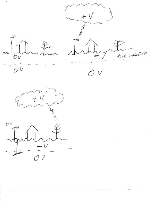
One of the most misunderstood features of grounding antenna structures such as a tower or something, is that people think that by grounding an antenna tower or pole, you are making it more likely that that tower will be struck by lightning by giving the lightning a path to ground. In actuality, you are making it LESS likely that the tower will be struck, because grounding the tower will give the static potential a path to ground. When a storm cloud approaches, the clouds will develop a high voltage, either positive or negative, and the largely non-conductive and poorly grounded surface of the soil, trees, and buildings under the cloud will develop an opposite potential, much like a big capacitor. Ie if true ground deep under the surface is zero volts, and the clouds are say a positive thousands of volts, the surface objects will have an "INDUCED" static voltage that can be thousands of volts opposite to the voltage in the clouds, ie negative if the clouds are positive, and positive if the clouds are negative. This makes the actual voltage differential twice the actual voltage in the clouds. By grounding an antenna tower or house or barn with lightning rods, etc, you are basically dissipating that induced static charge, putting your tower at ZERO volts rather than a high induced static voltage. This actually protects your house, not by giving the lightning a path to follow, but actually prevents your house or tower from being struck in the first place. Lightning will strike when the voltage differential between the clouds and the object gets up to a high enough value. If the clouds are say a positive thousand volts (it's much higher, but that's just an illustration), and your house is ZERO volts, and some tree hundreds of yards away is a negative thousands volts (again an illustration), the lightning is going to hit the tree, because the voltage differential between the ungrounded tree and the cloud will be 2000V divided by the distance to the cloud, compared to 1000V divided by the distance to the cloud, so the strike will hit the ungrounded tree, rather than the ungrounded house. Of course if you have a very high tower, that increases the chance of a strike by reducing the distance to the cloud, and tall towers suffer a lot of strikes, but grounding them actually decreases the odds of a strike, rather than increasing the odds.
Anyway, the point of the above is that grounding a house with lightning rods, or grounding a tower, is most effective by it's dissipating the induced static charge that preceeds a lightning strike, making a strike less likely, however I would not connect my receivers and other electronics to the tower ground unless that tower ground is bonded to the service ground. I believe they are best protected by their own house ground of the electronics being plugged into a grounded outlet. I really believe that you're better off not grounding your antenna at all if your tower or pipe isn't bonded to the service ground because if the antenna is grounded to a ground not bonded to the house ground, then you're likely to get high voltage differences between the two grounds. The second ground can still protect you by reducing the induced potential that your antenna will experience, even though you're not connected to it.

Just my opinion though, based on the assumption that most people are not going to follow NEC code to the letter, and just trying to suggest what I think is the safest way to deviate from the code.
 
Thanks

BJ, thank-you very much for the info.! Very nice looking dog by the way. I think what I will do is replace the 300 ohm "TV" twinlead ribbon with 75 ohm coax, ground the coax with a block just before it enters the house and ground the block to an outdoor electrical outlet. The only problem there is the converting of 75 to 300 ohms. My tuner has a 75 ohm female plug, DIN ?, (looks like a coax plug but isn't?), the only attaching DIN connectors I can find convert 75 to300 ohms or vice-versa. Before it was easy, I just used a balun to convert from 75 to 300 ohms at the back of the tuner for the trip on the 300 ohm twinlead to the cubical antenna, got many stations and was much happy. I tried using the baluns at both ends of the coax and got nothing (75 to 300 ohms at the tuner, then at the antenna end, 300 back to 75 ohms, can you even do that?) I need to check my coax cable, but I think its slim to none that it's the problem. Is there any way to ground twinlead? Sorry, I am truely babbling, but I believe I am almost to the end of my journey, thanks to you, of course, take care and thanks again...

MAC
 
.... My tuner has a 75 ohm female plug, DIN ?, (looks like a coax plug but isn't?), the only attaching DIN connectors I can find convert 75 to300 ohms or vice-versa. Before it was easy, I just used a balun to convert from 75 to 300 ohms at the back of the tuner for the trip on the 300 ohm twinlead to the cubical antenna, got many stations and was much happy. I tried using the baluns at both ends of the coax and got nothing (75 to 300 ohms at the tuner, then at the antenna end, 300 back to 75 ohms, can you even do that?) I need to check my coax cable, but I think its slim to none that it's the problem. Is there any way to ground twinlead? Sorry, I am truely babbling, but I believe I am almost to the end of my journey, thanks to you, of course, take care and thanks again...

MAC

Well, you've got me confused about my own system. :)
I have a tuner with a similar connector, kind of looks like a cross between an F-connector and an RCA connector. At first, I wasn't sure what to use to connect to it, but I finally just connected via one of those slip on F-connectors, ie an F-connector that doesn't have threads. This seemed to work, however I have a fairly strong signal, so I might not notice if there were problems.
Anyway, I never thought to look at the specs for the input. I just assumed that it was a 75 ohm connector. Interesting that it's apparently a 300 ohm connector.
Anyway, if it were me, I'd try using one of those slip on F-connector adapters, and not bother with the conversion back from 75 to 300 ohms. For a transmitter, the matching of the antenna is pretty important, but it is much less important for a receive only situation.
Anyway, thanks for the info re that connector being 300 ohm. I'll have to look for the connector with the balun you mentioned.
 
RE

Thanks for the info BJ, the 300-75 ohm conversions can get hairy, I tried using a coax on my AM side, I have the 2 screw standard hook up on the rear of my tuner, so I, remember now, a little knowledge can be a dangerous thing, I digest, well I used a balon to convert, 1st off, from the 2 screws on the rear of my tuner to a coax screw on, which meant I had to convert to 75 ohms and (is it nesessary to run only 75 ohms through a coax cable?) using a balon on the other end to convert back to 300 ohms figuring I needed to go back to 300 ohms for the 12"x12"x12"x12" loop antenna I built, well to make a long story short, I go less then zilch reception! Even with 300 ohm ribbon TV wire running to the roof I couldn't seem to beat the little loop job they give you which attaches to the rear of the tuner, with which I only get 2 stations, one of which is spanish, and I had 4 years of Spanish in high school.... On the FM side I seem to get pretty much similar results using 300 ohm TV cable or the coax, with balon on both ends of the coax for conversion & attachment hook up reasons. I am going with coax because I figure on getting better shieding and the ability to use a grounding block just before bringing it into the house (grounding the block to an outside electrical outlet), what do you think? Is that the best way to go? Do I even need to ground the cubical antenna if I remove the metal pole, have it attached to a porch 4"x4" colume on wooden dowels sticking up in the air about 16', 10' from the house, with the cubical being made of PVC & using insulated #8 wire?
Well thanks agian BJ, hopefully this will rap things up for the great antenna adventure and I'll be leaving you in peace......

MAC

P.S. I'm working on getting an image inserted of my Poms, hopefully they won't scare your collie.....
 
BJ, some helpful information given there on the lightning strikes and ground. I beg to differ, though, on some of it, but since it's all theory anyway, I don't consider it an arguement, just another viewpoint. As far as direct vs. indirect hits with lightning, both can be devastating, but I don't follow the potential induction thing. However, the results are what counts. A "near-miss" with lightning will induce a voltage into conductors (antenna wires, telephone lines, house wiring, etc.) by the same method that makes a transformer or generator work. A CHANGING electro-magnetic field (or plain magnetic field, which won't be caused by lightning) passing near a conductor will induce (generate) a voltage within the conductor. With the multi-thousand volts involved in a lighning strike, a very large voltage can be induced into nearby (within say 1/2 mile??) conductor as mentioned above and even metal piping, to include conduit as well as water/gas pipes. This is prevalent in hits that burn wires all the way to water pumps on farms and houses, etc.

Raising a metal tower and grounding WILL attract lightning that is going to strike nearby by giving a path to ground (or from ground, in some cases). The capacitor illustration you mentioned is pretty accurate, and the air/rain combination being the dialectric between the capacitive plates - clouds and earth. An uneven thickness in the dialectric will cause a path from one plate to the other at the nearest point. This will happen in the area where lightning would strike if the tower wasn't there. The protection comes by providing a path for MOST of the direct hit to/from ground instead of letting all or part of the path to be completed by antenna feedline, power line, or telephone wiring to the "house ground".

Grounding the shield side of the coax (and, as you stated, NOT the twin-lead) is more beneficial to reducing electrical noise from getting into the receiver than reducing lightning. The spark-gaps can cushion the blow, so to speak, of a nearby lightning strike, though probably won't be of much benefit to a direct hit. Actually, the antenna wiring burning up will probably be more beneficial than the gap, IN A DIRECT STRIKE.

I do agree that the antenna is probably not going to be a hazard unless it is mounted on a tall tower. In a case like that, it's a good idea to disconnect the antenna and keep the disconnected end away from ground, or grounded equipment when the weather is expected to get threatening. After the lightning starts popping IS NOT the time to grab the "lightning rod" and disconnect it!! Do it BEFORE the lightning starts.
 
BJ, some helpful information given there on the lightning strikes and ground. I beg to differ, though, on some of it, but since it's all theory anyway, I don't consider it an arguement, just another viewpoint.
Likewise, I realize my theory isn't popular, but I was introduced to it by a fellow who worked on very tall professional towers. I didn't believe at first, but the more I thought about it the more I was converted.
....... I don't follow the potential induction thing. However, the results are what counts. A "near-miss" with lightning will induce a voltage into conductors
....
I don't think I explained my theory well. When I used the word induced, I wasn't referring to a coil type induction, but a capacitor like induced polarization. Ie when one side of a capacitor gets a positive charge, the other plate acquires an induced negative charge. Basically the principle that like charges repel each other. If a cloud is negatively charged, it will repel electrons in the poorly conductive surface, and the surface will be positively charged, compared to a zero volt ground potential. If a cloud is positively charged, electrons will be attracted to the surface, giving the poorly conductive surface a negative charge.

Raising a metal tower and grounding WILL attract lightning that is going to strike nearby by giving a path to ground (or from ground, in some cases).
This path to ground issue only becomes important AFTER a lightning strike begins. For a lightning strike to begin, a couple things have to happen, and again, I think I referred to voltage differential, but perhaps voltage gradient would have been better. Basically, for a lightning strike to start, what has to happen is for a voltage gradient to increase to an extent where the normally non-conductive air breaks down into sort of a plasma of ions, which becomes conductive. Once this happens, then, and only then does the path to ground become important. The thing about the voltage gradient, which is basically a volts/distance parameter, is that this becomes higher via either increasing the voltage, or decreasing the distance. With all else being equal, putting up a tower decreases the distance to the cloud, so a tower is more likely to be hit by lightning. However if you GROUND the tower, you are reducing the voltage differential by a factor of two, thus decreasing the voltage gradient, making the tower LESS likely to be hit, if it is grounded. Depending upon how tall the tower, and how low the clouds, the tower may still be more likely to be hit, but the bottom line is that the voltage differential is less for a grounded tower, so grounding a tower makes a strike less likely.
I've drawn a couple pictures in the attachment below, showing off my first grade art ability. The first picture shows tower, house, and tree with no cloud, and the poorly conductive surface at zero volts. The 2nd picture shows a positive cloud, and an ungrounded tower, house and tree. Due to the capacitor polarization effect, the surface will become negatively charged, as will the ungrounded tower, house and tree, and the strike will go to the tower.
In the third picture, again the positive cloud, and negative surface, with negative tree and house, however the tower is now grounded, so it is zero volts instead of some negative polarized voltage. In this case, since the voltage differential is twice as high between the tree and the cloud (ie 2V/D instead of V/D ), the strike will go to the tree instead of the tower.

Anyway, that's the theory, which is really a collection of a variety of theories from people many of which come to different conclusions. Where the strike occurs depends on many factors, and isn't predictable, however I'm just trying to illustrate why grounding the tower is actually a good thing towards prevention.

a very large voltage can be induced into nearby (within say 1/2 mile??) conductor as mentioned above and even metal piping, to include conduit as well as water/gas pipes. This is prevalent in hits that burn wires all the way to water pumps on farms and houses, etc.

Speaking of water pumps.... about a year ago, we had a very nearby strike here. It did take out a couple of my receivers, thanks to a poorly installed DirecTV dish. But the amazing thing is that the lightning was looking for your "path to ground", and found the pipe on my water well. The well itself is about 500' deep, but the metal pipe only goes down 30' or so into the bedrock I think. But when the lightning hit that pipe, it scoured off all the rust and other deposits on the well casing, and perhaps off the sides of the hole in the rock. I went to wash my hands a bit after the strike, and the water was a deep red-purple-brown color. Couldn't even see through a glass of the water. I ran the water for about 45 minutes, and it cleared up quickly, but that was amazing. Didn't hurt the water pump at all, it just cleaned off the pipe. :)

Anyway, I just wanted to explain my theory better. I realize not many if any people will be convinced, but I am. :)
 

Attachments

  • lightning.jpg
    lightning.jpg
    114.7 KB · Views: 88
I will weigh in on this a bit, when it comes to lightning strike prevention there is a good paper by William Rison that I have attached as a PDF. He does make the case for lightning protection with the tests preformed by him and others at the Langmuir Laboratory over the last 35 years.
Note that NFPA has backed out of the prevention side of regulation, IMHO NEC should as well. The 17 gauge steel messenger wire requirement should be removed from the NEC. I would also support the removal of the required grounding of the coax by NEC, I don't believe coax grounding is a life or fire safety issue.
Bob
 

Attachments

  • magic.pdf
    30.9 KB · Views: 93
WOW!!!! Thank-you fellows! Soooo, I am going with the coax cable, block grounded just before entering the house to the outside electrical outlet ground, and I will keep the antenna unpluged at the rear of the tuner while not in use? May your clouds be freindly...

MAC
 
Bigmac96, sorry to get side-tracked and seemingly leave you out :). Ha, try to ask a simple question and get a seminar :confused:. I hope you got something out of this, I did, quite an interesting discussion.

Wescopc, thanks for the pdf file on lightning studies, very interesting, to say the least. I saw some of the streamer studies done with small rockets on a TV program. That too, was interesting. Thanks so much for bringing that, at least I enjoyed it and sure others did too.

Bj, great viewpoints. All the info put together will give all a better appreciation for the forces of nature that none of us will completely understand, at least I don't think we'll ever get a FULL understanding.

I would like to add just one small thing that may be of help to somebody. When setting up amateur radio repeaters, we generally use a hardline (coax, but not flexible like what most are used to, more like - and usually is -- aluminum encased feedline like used for television cable company lines to send signals to the customers). When we reach the bottom of the tower and just before the receiver, or outside the building that houses the repeater when we're lucky enough to have one, we "roll" the feedline into about two loops, or so, to act as an inductor to resist high frequency surges (rapid static discharge we call lightning) from travelling down the line into the tranceiver. Though probably not very effective for a direct strike, I have no reason to doubt that it helps in near-misses or lightning strikes that travel down the tower to a less restrictive path to ground (here we go again?).

Thanks for the interesting exchange of ideas and documents.

Bill
 
Status
Please reply by conversation.

Users Who Are Viewing This Thread (Total: 0, Members: 0, Guests: 0)

Who Read This Thread (Total Members: 1)