
I posted a thread earlier in June about receiving a Moteck SG2100 with a 50mm neck rather than a 42mm neck. The short version of that story is that the original eBay seller is refusing to communicate, an internet storefront for a satellite shop doesn't communicate with prospective customers of a 42mm neck, and Moteck doesn't respond to customer inquiries.
In the spirit of not getting mad but getting even, I set about to design a workaround for integrating a 50mm neck with a 42mm collar. Please note that I'm an engineer in Canada and most references will likely be in SI units. For those wanting to do casual arithmetic at home, it's 25.4mm per inch. Haha.
Initial Bill of Materials:
- 1 Moteck SG2100 antenna motor with 50mm neck
- 1 Azure Shine 85cm DTH Ku reflector with J pole mount and 2 support struts (https://www.azureshine.com.tw/upfiles/editor/files/85cm.pdf)
- 2 double antenna mast clamps (V jaw block, 140mm / 5.5" threaded rod) (Amazon part B096X145NN)
- 1 spare 42mm J pole
- 1 wood pallet
- assorted lag screws, power tools, hand tools, bubble level, wood for cribbing
Basic Method of Procedure for Initial Fitment:
- find a mostly-level spot for the pallet, as this work will be easier and safer to piece together at grade than on a roof
- build up the reflector, per manufacturer's instructions
- fasten the J pole and struts to the pallet in a manner such that the installation is as plumb and as level as practically possible
- zero the azimuth of the SG2100
- install the SG2100 on the J pole, per manufacturer's instructions
- do not set the elevation of the motor yet
- install the upper and lower jaw blocks (4 blocks total; 2 per position) on the 50mm neck
- adjust center of jaw blocks to be at the zero azimuth on the neck
- hand-tighten the clamps so there is a tiny amount of play on the 50mm neck
- install the 42mm J pole into the antenna mounting collar and fasten into place
- install the 3rd jaw block onto the mounting rod at the top and bottom positions
- with the motor elevation bolts and dish elevation bolts loosened and the reflector notionally close to a vertical orientation, bring the 42mm pole back into the 3rd jaw blocks
- use wood cribbing if required under the bottom lip of the reflector for help in elevation
- install the 4th jaw block at the top position and get a few threads into the nuts to prevent the dish from pivoting forward
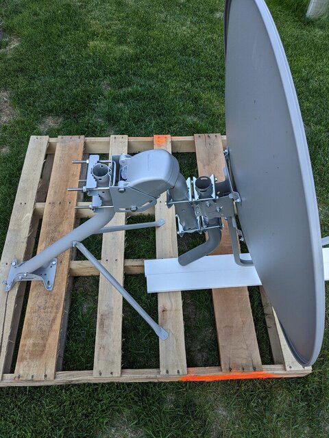
- install the 4th jaw block at the bottom position and fasten into place
This is the basic fitment. This took about an hour to put together. As none of the bolts or nuts are tight, there is going to be ample opportunity to rotate on two axes for each of the motor and of the dish, so keep this in mind. The 42mm J pole also has a bolt through it and the reflector bracket, hence why there are currently no bolts to secure the 42mm collar. No other work has been performed to check orientations or to dial in site-specific parameters for elevation, declination, etc. Nothing has been energized either.
There are some observations in this setup:
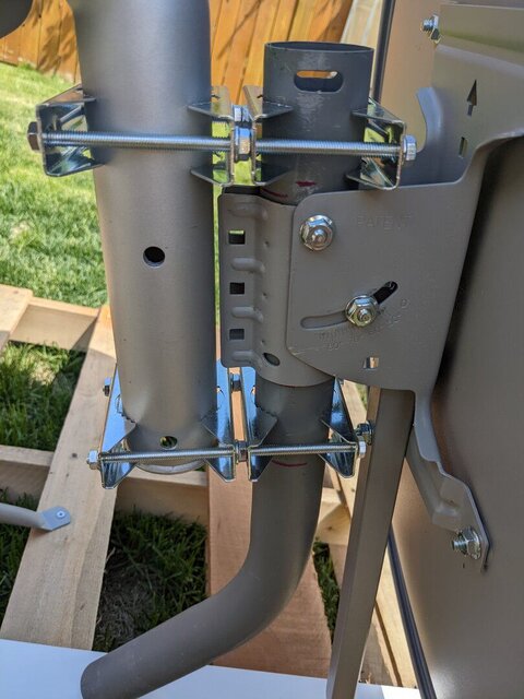
- the rods for the mast-to-mast clamps are just barely long enough
- to make the rods work, only one nut is used on each side of the 50mm neck
- the rods would ideally be 152mm / 6.0" or longer
- this middle nut cannot be avoided because the fastening points at the back of the 42mm collar will have an interference with the 50mm neck
- the middle nut is effectively a spacer
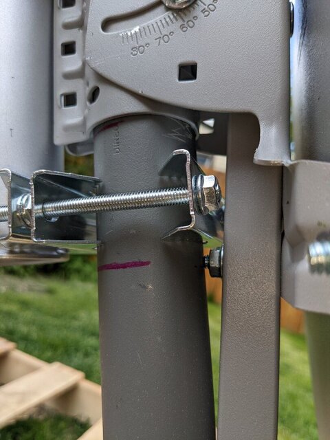
- because the 42mm J pole has not been cut to length, it becomes obvious that for certain positions of the lower clamps, there will be interference from the LNB arm's lower bolt
- the lower clamps will need to move up as high as possible
- the 42mm J pole will need to be cut at a point above the travel of the LNB arm bolt
- even if the LNB arm bolt is clear of the bottom of the shortened 42mm neck, the new points of interference will be the bottom of the reflector elevation bracket with the top edge of the jaw block and a point above the LNB arm bolt on the arm itself with the flat face of the jaw block
- the photos show the reflector elevation from the "B" side so the angles shown need to be taken with a grain of salt
My inference is that this particular setup with this style of reflector mount might not work for certain latitudes because of the mechanical interferences. This setup is also subjected to a number of moments of force that are likely to affect long-term usability. Beyond the standard bolts that are locked for elevation settings, the lower clamp set is needed to keep the 42mm neck level and plumb. Because the attachment point to the Moteck has been moved out on a longer radius and the mass has increased, the motor is going to see a different moment. I will need to keep an eye to see if there are any implications on gear backlash. I am also thinking that some lock washers might be advantageous on the elevation bolts. Finally, due to the rod length, the use of thread locker might be a consideration for the final orientation.
Due to some other commitments, I likely will not be able to get back to this project for about 4 weeks. I will update this thread when I have a chance.
Any constructive comments and criticisms are appreciated. Everyone else's mileage may vary.
In the spirit of not getting mad but getting even, I set about to design a workaround for integrating a 50mm neck with a 42mm collar. Please note that I'm an engineer in Canada and most references will likely be in SI units. For those wanting to do casual arithmetic at home, it's 25.4mm per inch. Haha.
Initial Bill of Materials:
- 1 Moteck SG2100 antenna motor with 50mm neck
- 1 Azure Shine 85cm DTH Ku reflector with J pole mount and 2 support struts (https://www.azureshine.com.tw/upfiles/editor/files/85cm.pdf)
- 2 double antenna mast clamps (V jaw block, 140mm / 5.5" threaded rod) (Amazon part B096X145NN)
- 1 spare 42mm J pole
- 1 wood pallet
- assorted lag screws, power tools, hand tools, bubble level, wood for cribbing
Basic Method of Procedure for Initial Fitment:
- find a mostly-level spot for the pallet, as this work will be easier and safer to piece together at grade than on a roof
- build up the reflector, per manufacturer's instructions
- fasten the J pole and struts to the pallet in a manner such that the installation is as plumb and as level as practically possible
- zero the azimuth of the SG2100
- install the SG2100 on the J pole, per manufacturer's instructions
- do not set the elevation of the motor yet
- install the upper and lower jaw blocks (4 blocks total; 2 per position) on the 50mm neck
- adjust center of jaw blocks to be at the zero azimuth on the neck
- hand-tighten the clamps so there is a tiny amount of play on the 50mm neck
- install the 42mm J pole into the antenna mounting collar and fasten into place
- install the 3rd jaw block onto the mounting rod at the top and bottom positions
- with the motor elevation bolts and dish elevation bolts loosened and the reflector notionally close to a vertical orientation, bring the 42mm pole back into the 3rd jaw blocks
- use wood cribbing if required under the bottom lip of the reflector for help in elevation
- install the 4th jaw block at the top position and get a few threads into the nuts to prevent the dish from pivoting forward
- install the 4th jaw block at the bottom position and fasten into place
This is the basic fitment. This took about an hour to put together. As none of the bolts or nuts are tight, there is going to be ample opportunity to rotate on two axes for each of the motor and of the dish, so keep this in mind. The 42mm J pole also has a bolt through it and the reflector bracket, hence why there are currently no bolts to secure the 42mm collar. No other work has been performed to check orientations or to dial in site-specific parameters for elevation, declination, etc. Nothing has been energized either.
There are some observations in this setup:
- the rods for the mast-to-mast clamps are just barely long enough
- to make the rods work, only one nut is used on each side of the 50mm neck
- the rods would ideally be 152mm / 6.0" or longer
- this middle nut cannot be avoided because the fastening points at the back of the 42mm collar will have an interference with the 50mm neck
- the middle nut is effectively a spacer
- because the 42mm J pole has not been cut to length, it becomes obvious that for certain positions of the lower clamps, there will be interference from the LNB arm's lower bolt
- the lower clamps will need to move up as high as possible
- the 42mm J pole will need to be cut at a point above the travel of the LNB arm bolt
- even if the LNB arm bolt is clear of the bottom of the shortened 42mm neck, the new points of interference will be the bottom of the reflector elevation bracket with the top edge of the jaw block and a point above the LNB arm bolt on the arm itself with the flat face of the jaw block
- the photos show the reflector elevation from the "B" side so the angles shown need to be taken with a grain of salt
My inference is that this particular setup with this style of reflector mount might not work for certain latitudes because of the mechanical interferences. This setup is also subjected to a number of moments of force that are likely to affect long-term usability. Beyond the standard bolts that are locked for elevation settings, the lower clamp set is needed to keep the 42mm neck level and plumb. Because the attachment point to the Moteck has been moved out on a longer radius and the mass has increased, the motor is going to see a different moment. I will need to keep an eye to see if there are any implications on gear backlash. I am also thinking that some lock washers might be advantageous on the elevation bolts. Finally, due to the rod length, the use of thread locker might be a consideration for the final orientation.
Due to some other commitments, I likely will not be able to get back to this project for about 4 weeks. I will update this thread when I have a chance.
Any constructive comments and criticisms are appreciated. Everyone else's mileage may vary.

")
