Which of these 2 ACTUATORS is Best for a 12 Ft Dish?

  • WELCOME TO THE NEW SERVER!

    If you are seeing this you are on our new server WELCOME HOME!

    While the new server is online Scott is still working on the backend including the cachine. But the site is usable while the work is being completes!

    Thank you for your patience and again WELCOME HOME!

    CLICK THE X IN THE TOP RIGHT CORNER OF THE BOX TO DISMISS THIS MESSAGE
Status
Please reply by conversation.

jsattv

SatelliteGuys Pro
Original poster
Jul 4, 2006
1,061
8
My current Actuator on my 12 Foot Mesh Dish will not work with my V Box III as it appears to be some type of 5 wire Optical Sensor.

I have have collected 2 used Actuators - see picture # 1. I thought one was not working but the longer one is in fact working when I connect my 12 VDC Battery Charger to it. The specs for both used units are as follows:

1) A Von Weise Actuator recovered last year from a scrapped 12 Ft Dish:
Model V 76-5
24-36 VDC
1/15 HP
2.75 Amp
19:1 Ratio
Serial L243
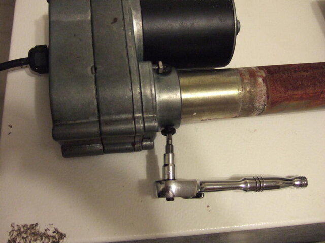
Also see pictures2 & 3 for more closups of this V 76-5 Von Weise Actuator.

2) A Fasco Hawker Siddley unit (it's also marked with a Von Weise Label on the side) was recovered from a 7.6 Unimesh Dish
Model V00099BB75
36 VDC
1/15 HP
2.75 Amp
Serial L229
MTR RPM 1550

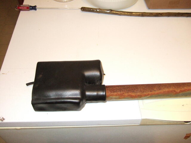
The second unit used to work with a 7.6 Ft Unimesh Dish and I recovered it in Feb. But it has been disconnected for many years. It has a type of pivot bearing on it - see pic # 4. I haven't been able to test this unit on the Bench as Gabshere advised me it needs to be locked down or mounted on a dish to be able to test it. When I hooked up the Battery Charger to it - it started to move in a circular motion.

Both Actuators appear to be 4 wire units - see pics #2 and #5, so it looks like they may work with my V Box III Dish Controller.

Can anyone advise me as to which is the Best Actuator to connect up to my 12 Footer Mesh Dish? Any comments would be greatly appreciated.
 

Attachments

  • DSC00942.JPG
    DSC00942.JPG
    615.1 KB · Views: 1,107
  • DSC00946.JPG
    DSC00946.JPG
    614.2 KB · Views: 1,179
  • DSC00939.JPG
    DSC00939.JPG
    318.6 KB · Views: 773
  • DSC00935.JPG
    DSC00935.JPG
    459.9 KB · Views: 746
  • DSC00949.JPG
    DSC00949.JPG
    551.5 KB · Views: 844
When i look at both they almost look the same model....... maybe one is probably a earlier version or a version that von weise sold without their name..... but if you look closer at each
one has 4 magnets on a wheel that pass over the sensor and the other has eight magnets.
these magnets will count as they cross the sensor and report back to the v-box so the one with eight magnets will count twice as much.... making it twice as accurate in movement. so i would pick the one with eight magnets.
 
The one with 8 magnets looks like it's on the motor at the top of picture #1. I would swap arms and use the arm on the bottom with the 8 magnet motor. The top one is rusted more and it has no bearing at the mount clamp which will add some undue stress to the motor and the VBox.
 
The one with 8 magnets looks like it's on the motor at the top of picture #1. I would swap arms and use the arm on the bottom with the 8 magnet motor. The top one is rusted more and it has no bearing at the mount clamp which will add some undue stress to the motor and the VBox.

Thanks Gabshere and ACRadio. ACRadio how would I swap out the arms? Just undo the screws at the Top of the arm shaft? Since I have never taken an Actuator arm apart before, I am a bit worried that I may damage something and have nothing left to work with!! Do I really need to know what I am doing to do this arm shaft swap out??
 
As opposed to swapping motors I would probably just swap magnet wheels. When swapping motors consideration has to be given to the mechanical limit switches so it would probably be easier to just make the 4 magnet motor into an 8 magnet one.
 
As opposed to swapping motors I would probably just swap magnet wheels. When swapping motors consideration has to be given to the mechanical limit switches so it would probably be easier to just make the 4 magnet motor into an 8 magnet one.

ACRadio is correct in that is the path of least resistance. :)

Swapping out the motor heads isn't hard either.

If you have any mechanical abilities at all, after swapping out the heads, you can hook the actuator up on a table with your analog box, and run it back and forth. You will see two little lobes near the limit switch that look like a small camshaft. Just loosen the bolts that hold them and twist to where you want the switch to turn off the power. :)

On a Von Weise, there are 3 small bolts that hold the shaft into the motor head. They are the star kind which means ordinary screw drivers won't work. Once those are out, the collar should slip right up the shaft. You may have to give the shaft a little encouragement to get it to come loose. It is a yoke/pin that drives the worm gear, so it should slip right off.

Piece of cake! :)

Thanks a lot for the knowledgable replies ACRadio and Linuxman. Not wanting to make this too complicated..... BUT is there another option in taking down my 5 wire Actuator currently in use on my 12 footer (it only partially /slightly moves when I put power to it with the V BOX III)? Right now I can only move my 12 Foot Mesh Dish from Satellite to Satellite on the current actuator with a 12 VDC Battery Charger. It did stick once in the way Easterly direction and the Battery Charger wouldn't move it, when it was snowing in February and I had one heck of a time lifting it up and rocking it until I finally freed it up. Could I also INSTALL the 8 magnet unit on this Current Actuator - see picture. That is, change out my current Actuator that is now in use from a 5 wire Optical Sensor to a 4 Wire Actuator??
 

Attachments

  • DSC00756.JPG
    DSC00756.JPG
    1,013.8 KB · Views: 532
Well we don't know what kind of actuator it is. It will need to be a Von Weise or the parts won't mount correctly. If it's a Von Weise then just rip the sensor and magnet wheel out and mount it.
 
Last edited:
i suspect that all three are vonweise type and should swap over .
let me take my motor down and i will take some pictures of how to do the swap
 
i suspect that all three are vonweise type and should swap over .
let me take my motor down and i will take some pictures of how to do the swap

Thanks Gabshere those pictures for doing the swap would be great!! ACRadio & Gabshere, yes it is a Von Weise Actuator currently on the Dish the specs are as follows:
Model# V00099BE76
Serial J287
36 VDC
2.75 Amp
1/15 HP
19:1 Ratio
Von Weise W Gear Co. St Clair, Missouri
Also don't know if this means anything but when I bench tested with the 12 VDC Battery Charger before mounting it on the Dish, it I noticed that it did NOT Click when it moved - just a silent movement when running it each way.

Last fall I bought the complete system 2nd hand with the 12 Ft Mesh Dish, Von Weise Actuator, Tripod Steel Post, and Uniden 9900 Receiver which does NOT work for 36 VDC Power. The Polorotor however does work. The wiring for this Actuator on the Dish is as follows:
+ and - 36 VDC (heavier gauge Red and Black wires)
B for 12 VDC Sensor Power - Orange wire,
SEN for Sensor Return - Brown Wire,
GND for Sensor Ground - Grey Wire

I have the Uniden 9900 Instruction Manual which lists out the above wiring for the current Actuator on the Dish. Since the Uniden 9900 receiver didn't work for + and - 36 VDC I got a V BOX III but it is only for 4 wire connections.

Someone advised me that my Actuator has an Optical Sensor and thus needs 5 wires to work!! To get the 36 VDC to work the 9900 Manual said to try resetting some type of Circuit Breaker at the back of the Uniden 9900 Outboard Power Supply but it does absolutely nothing! I have tried every combination of wiring with this Actuator and NOTHING has worked - except when connected to my Viewsat Receiver in DisEqC 1.2 Motor Powering Mode I can get it to just slightly move the Actuator & see the Blue Light on the V Box click in but then it just quits?? So I 'm thinking that I need to retrofit my existing Actuator or try another refurbished Actuator with my V Box III. Any comments would be appreciated.
 
how to remove the shaft from a actuator

1) pic #1 actuator ready to remove motor
2) pic #2 move dust cover off motor
3) pic #3 remove three screws that hold motor & shaft together use a star type adaptor or a large flathead screw driver should fit also.
4) pic #4 all three screws removed
5) pic #5 slowly remove shaft from motor exposing worm/screw drive
6) pic #6 shows pin connecting motor to worm/screw drive
7) pic #7 shows pin connecting motor to worm/screw drive
8) pic #8 shows shaft will extend all the way off the actuator exposing the internal shaft or the part of the arm that moves the dish ( this one has some grease on it)
9) pic #9 shows the pin mostly removed. i tapped it out with a hammer and tap or you can use a small screwdriver ( one with a blunt point)
10) pic #10 shows pin removed
11) pic #11 shows pin removed beside a penny for size comparison
12) pic #12 shows pin removed from shaft. place a screwdriver in the eye bolt at the end of the arm ( see picture # 13) and use the outer shaft to tap against the screwdriver to tap the shaft from the motor shaft drive.
13) pic #14 & 15 screw shaft removed from motor
14) pic #16 shows the bushing which will need some grease ( try to get some on both sides of the bushing.

alltogether it took about 5 minutes :) it took longer to remove the actuator from the dish :)
hope this helps
 

Attachments

  • 10.JPG
    10.JPG
    49.1 KB · Views: 826
  • 9.JPG
    9.JPG
    62.2 KB · Views: 844
  • 8.JPG
    8.JPG
    59.5 KB · Views: 839
  • 7.JPG
    7.JPG
    55 KB · Views: 815
  • 6.JPG
    6.JPG
    43 KB · Views: 826
  • 5.JPG
    5.JPG
    58.2 KB · Views: 807
  • 4.JPG
    4.JPG
    58.5 KB · Views: 817
  • 3.JPG
    3.JPG
    65.8 KB · Views: 879
  • 2.JPG
    2.JPG
    56.7 KB · Views: 803
  • 1.JPG
    1.JPG
    49.6 KB · Views: 818
  • 15.JPG
    15.JPG
    63.5 KB · Views: 844
  • 14.JPG
    14.JPG
    69.4 KB · Views: 845
  • 13.JPG
    13.JPG
    53.5 KB · Views: 794
  • 12.JPG
    12.JPG
    68.2 KB · Views: 859
  • 11.JPG
    11.JPG
    39.3 KB · Views: 779
  • 16.JPG
    16.JPG
    58.4 KB · Views: 793
1) pic #1 actuator ready to remove motor
2) pic #2 move dust cover off motor
3) pic #3 remove three screws that hold motor & shaft together use a star type adaptor or a large flathead screw driver should fit also.
4) pic #4 all three screws removed
5) pic #5 slowly remove shaft from motor exposing worm/screw drive
6) pic #6 shows pin connecting motor to worm/screw drive
7) pic #7 shows pin connecting motor to worm/screw drive
8) pic #8 shows shaft will extend all the way off the actuator exposing the internal shaft or the part of the arm that moves the dish ( this one has some grease on it)
9) pic #9 shows the pin mostly removed. i tapped it out with a hammer and tap or you can use a small screwdriver ( one with a blunt point)
10) pic #10 shows pin removed
11) pic #11 shows pin removed beside a penny for size comparison
12) pic #12 shows pin removed from shaft. place a screwdriver in the eye bolt at the end of the arm ( see picture # 13) and use the outer shaft to tap against the screwdriver to tap the shaft from the motor shaft drive.
13) pic #14 & 15 screw shaft removed from motor
14) pic #16 shows the bushing which will need some grease ( try to get some on both sides of the bushing.

alltogether it took about 5 minutes :) it took longer to remove the actuator from the dish :)
hope this helps

Great Wonderful pictures and Step by Step Explanations George. This should be set up as a permanent "Actuator Shaft Disassembly Instruction". I Just copied the pictures and your explanation - fantastic!! So now I can transfer the 4 wire - 8 Magnet Actuator housing to the Roller Bearing 7.6 Ft Dish Actuator Shaft, or over to the Actuator Shaft on my existing Dish, thanks a lot for all your hard work!! That's what makes this Satellite Forum such a Great Help Site.
 
I have tried every combination of wiring with this Actuator and NOTHING has worked - except when connected to my Viewsat Receiver in DisEqC 1.2 Motor Powering Mode I can get it to just slightly move the Actuator & see the Blue Light on the V Box click in but then it just quits??

Let me explain why it "quits". It is actually a safety feature built into dish positioners. A reed switch (2 wire) sensor uses magnets on a wheel driven by the motor itself, and when one of the magnets passes by the reed switch it closes a set of contacts (the "reed") inside the switch. When the switch closes it shorts out the 2 wires connected to the switch, and it does this each time a magnet on the wheel passes it. The positioner counts each time the wire is shorted out, and it calculates the number of shorts (pulses) between each satellite and stores that number. Say for instance if Galaxy 16 is stored at 573 and you want to go to Galaxy 25 stored at 657 then the positioner knows to count 84 "shorts" in the wire then stop...and the dish will be at Galaxy 25. Here's the catch...if the motor is told to move and the positioner doesn't count any shorts in the sensor wires then it immediately stops because it knows there is a problem...either the motor isn't moving or the sensor isn't counting...it can't tell the difference. If the motor IS moving and it doesn't stop it could drive your dish into the ground.

An optical sensor works similarly. A wheel with holes around the rim is positioned between a light beam and a sensor. Each time a hole passes, the sensor sees the light beam and the positioner counts these just like a magnet passing a reed switch. The reason for the extra wire for the optical sensor (as well as for a Hall-effect sensor) is the optical sensor needs power to operate so there has to be a 5 or a 12 volt line going out to the sensor.

Thanks ACRadio for the very detailed explanation. Well I know that the current Von Weise Actuator Motor on the 12 Footer is working - because I can run it with the 12 VDC Battery Charger connected to the Red and Black wires inside House. Previously the Internal Limit switches (Mechanical Limits??) on the Actuator itself would cut off the Power at the extreme East & West Direction, but in Feb I wasn't watching close enough and as you mentioned I nearly ran the Dish off the end in the Easterly direction. I had a really tough time manually lifting it and rocking the Dish (it took what seemed like 1/2 an hour) until I could finally get the Battery Charger to run it again. Since then it has stuck in the Westerly direction one time so I sprayed the whole shaft with Jig a LOO Lubricant spray. Maybe this is reason enough to swap out the this existing Actuator and install the 8 Magnet Actuator with the other 7.6 Ft Dish Actuator shaft re Gabshere's instructions??

How To Setup V Box III Limits?
I'll be the first to admit I never have yet been able to set up the Electrical Limits with the V Box III yet since I couldn't get the Dish to move even when pressing the Manual East or West Buttons on the V Box III. Do these Electrical Limits have to be set up before doing anything else?

Also wouldn't the plan of replacing or modifying this 5 wire Actuator with a 4 wire Actuator be the best way to go? Trying to recover from the Flu Bug with all the gardening outside these last 5 - 6 days, so any reply(s) would be greatly appreciated.
 
I'll be the first to admit I never have yet been able to set up the Electrical Limits with the V Box III yet since I couldn't get the Dish to move even when pressing the Manual East or West Buttons on the V Box III. Do these Electrical Limits have to be set up before doing anything else?

the way i do it is set them first off...... then start setting up the satellites in memory ...
i do also like the mechanical limit switch in the motor itself but havent been able to find the time to go out and adjust on them. but i did mark the shaft when i had it apart to show my limit on the east side . the limit on the west side will stop itself.

after taking apart my actuator i found a gap larger than i suspect it should have been on the 8 magnets and the sensor ( i've been having troubles with counting on the v-box). i found the magnets were about 3/8 inch from the sensor so a pried the round magnet holder off and lightly oiled the plastic holder and replaced it lightly tapping it with a hammer until it was about 1/8 inch above the sensor . so this method would work in your swaps 4 magnets for 8 magnet wheel and would be lots easier than taking the whole thing apart.

but yes continue the swap out of the 5 wire sensor actuator which the v-box can't control to one a v-box can control. you will love it once you get it working right :)
I hope you get to feeling better soon :)
 
Well the 25 year old Saginaw on the 10 foot Channel Master finally bit the dust. I knew I had a bunch of Von Weise parts and I also knew that if I could find a good motor that I had enough other parts to make a complete actuator. This positioner uses a 10 turn pot sensor and I saw I had parts for both kinds. The first motor I tested had a 10k 10 turn pot and it worked great! I found a good set of shafts so I greased it up while it was apart and now have a working Von Weise to replace the Saginaw.
 
Well the 25 year old Saginaw on the 10 foot Channel Master finally bit the dust. I knew I had a bunch of Von Weise parts and I also knew that if I could find a good motor that I had enough other parts to make a complete actuator. This positioner uses a 10 turn pot sensor and I saw I had parts for both kinds. The first motor I tested had a 10k 10 turn pot and it worked great! I found a good set of shafts so I greased it up while it was apart and now have a working Von Weise to replace the Saginaw.

ACRadio, very nice dish farm. What kind of grease is needed for the Actuator arm?? Some type of Gear grease?
 
ACRadio, very nice dish farm. What kind of grease is needed for the Actuator arm?? Some type of Gear grease?

Nah...any good lithium grease will do fine. I had a mini tube of grease that fits in those small grease guns and I just popped the top on that....it's another thing I had saved over the years. I remembered having it a couple of months ago but I forgot where I put it and bought another grease gun to grease the actuators. I was looking for my box of old sat magazines the other day (see the Memory Lane thread) and ran across the tubes of grease. The moral of this story is...save everything, just remember where you put it! You will never know when you might need actuator parts or a tube of grease... :)
 
Nah...any good lithium grease will do fine. I had a mini tube of grease that fits in those small grease guns and I just popped the top on that....it's another thing I had saved over the years. I remembered having it a couple of months ago but I forgot where I put it and bought another grease gun to grease the actuators. I was looking for my box of old sat magazines the other day (see the Memory Lane thread) and ran across the tubes of grease. The moral of this story is...save everything, just remember where you put it! You will never know when you might need actuator parts or a tube of grease... :)

Thanks ACRadio. I do have a big Plastic Container of a type of White Lithium Grease I bought years ago at a Canadian Tire Store up here... you just scoup it up with your hands and put it on - Car Door Hinges, etc, etc, but it doesn't go in a Grease Gun, will that work?
 
Thanks ACRadio. I do have a big Plastic Container of a type of White Lithium Grease I bought years ago at a Canadian Tire Store up here... you just scoup it up with your hands and put it on - Car Door Hinges, etc, etc, but it doesn't go in a Grease Gun, will that work?

Sure will. I had mine apart which means the outer tube was taken off the motor and the inner tube was screwed all the way off the acme screw. I smeared grease all up and down the acme screw, then coated the inner tube with a thin layer because there was some rust on the outside. If I was real industrious I would take a wire brush that mounts on a drill and brush out the inside of the outer tube and put a little coat on that. And if I was just super industrious I would take the back housing off and put a little grease in the gearbox. These motors go through a lot of stress, having to move a heavy dish in the heat and cold, in the wet and dry. Anything that can be done to make it's job easier will help provide a longer life and less maintenance.
 
Status
Please reply by conversation.

Users Who Are Viewing This Thread (Total: 0, Members: 0, Guests: 0)

Who Read This Thread (Total Members: 6)