Design & Construction of Offset Dish

Status
Please reply by conversation.

nelson61

SatelliteGuys Master
Original poster
Lifetime Supporter
Dec 8, 2007
8,247
7,906
Where it's Warm
Thought I might share some work in progress on the design and construction of an offset dish (a little bigger than most would use).

As most obsessions, this one started out as a minor irritant ( I lost reception on some transponders due to low signal levels).

That led to the world of satelliteguys.us and the associated technology discussed in the forums. Stuff like line losses, dBm, receiver thresholds and noise levels (noise is really important with low signal levels).

That led to the need to know the radiation levels in my receiving area. Onward from there to learning about the FCC data bases, finding the digital data for EIRP's and converting it into Google Earth format ( this is really neat since you can overlay satellites and transponder EIRP's for any geographic point in the FCC data base on the google earth model and rotate and zoom to your hearts content).

All that "stuff" convinced me that I needed a "BIGGER DISH". AHH, the dream of every addict.

On again to more searches on the principles of offset antennas and the associated formulas. And, a side trip to learn how to use AutoCad . This mother has to have tolerances that could be used on the Hubble (I wish).

Now for some modeling to aid in construction design.

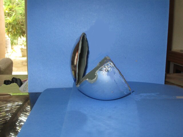
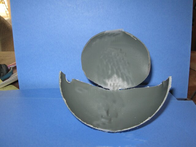
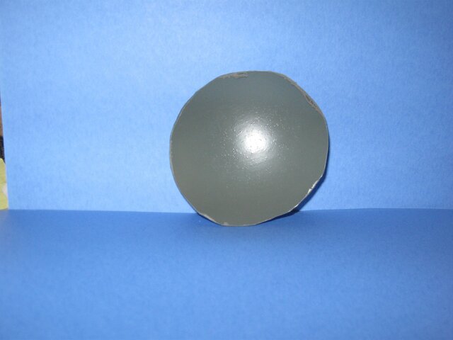
I needed to visualize what I needed to do and started out with half of a 5 inch model ball which simulated a prime focus antenna. Then I cut it up to illustrate the part that would be used for the offset antenna.

The math all works out that (more or less) when you cut an offset out of a 0.3 F/D prime focus you end up with a offset antenna with an F/D of 0.6.

Model pictures attached .

Next, I'll get into design layout and construction (in progress).
 

Attachments

  • Prime Focus with Offset Cut.jpg
    Prime Focus with Offset Cut.jpg
    526.6 KB · Views: 940
  • Prime Focus with Offset Front.jpg
    Prime Focus with Offset Front.jpg
    489 KB · Views: 1,140
  • Prime Focus Offset.jpg
    Prime Focus Offset.jpg
    301.2 KB · Views: 777
  • IMG_0047.jpg
    IMG_0047.jpg
    582.5 KB · Views: 566
Which Hubble Story ?

Speaking of the Hubble Space Telescope...

I have heard (now) three stories on how that mirror problem came to be. I think the stories evolve as each group of engineers comes up with a story to cover their particular rear end.

The major blame can be placed squarely on arrogance. Had they done a simple Foucault test, they would have detected the problem before launch. Every amateur astronomer who has ground a telescope mirror has to use this test to check his/her mirror.

[ame="http://en.wikipedia.org/wiki/Amateur_telescope_making"]Amateur telescope making - Wikipedia, the free encyclopedia@@AMEPARAM@@/wiki/File:Telescope_trailer_22.jpg" class="image"><img alt="" src="http://upload.wikimedia.org/wikipedia/commons/thumb/a/a7/Telescope_trailer_22.jpg/220px-Telescope_trailer_22.jpg"@@AMEPARAM@@commons/thumb/a/a7/Telescope_trailer_22.jpg/220px-Telescope_trailer_22.jpg[/ame]

Sorry to wander off topic like this
 
Wouldn't be get more _efficient_ antenna by using parabolic surface, rather then spheric one ? ;)

Absolutely

As I understand it, the dishes we commonly use are part of a parabolic reflecting surface. If you took a BUD and started at the center and went out to the edge in an arc and then back in to the center with an arc you would have described the offset dishes we use.
 
The layout

Early on a stumbling block was how to draw the parabolic curve. After much struggling, I found a site in Italy that had a neat little program that would import the data. A little more struggling and the elliptical shape was detailed and I could start doing the takeoffs for arc and cord lengths.

I have gotten up in the night more than once to check the calculations. I don't know which dream is worse, the Hubble lens error or the Mars shot where Texas and California engineers used English units for part of the calculation while the other used Metric and then mixed them (needless to say , it missed). They say a little paranoia is healthy but I am not too sure about that anymore.

Next; method and materials of construction - this is where it gets expensive.
 

Attachments

  • offset parabolic layout Model .pdf
    7.6 KB · Views: 775
Although a bit light-hearted, I seriously suggest you read this similar thread on home-brew dishes in the BUD section.
The links given, are invaluable... at least the ones I posted are. - :cool: - :D

happy holidays
 
Early on a stumbling block was how to draw the parabolic curve. After much struggling, I found a site in Italy that had a neat little program that would import the data. A little more struggling and the elliptical shape was detailed and I could start doing the takeoffs for arc and cord lengths.

I have gotten up in the night more than once to check the calculations. I don't know which dream is worse, the Hubble lens error or the Mars shot where Texas and California engineers used English units for part of the calculation while the other used Metric and then mixed them (needless to say , it missed). They say a little paranoia is healthy but I am not too sure about that anymore.

Next; method and materials of construction - this is where it gets expensive.

Nelson61:

In your first post you stated, "The math all works out that (more or less) when you cut an offset out of a 0.3 F/D prime focus you end up with a offset antenna with an F/D of 0.6." I don't know where you got your information, but the offset dish will have the same focal point as the larger prime focus from which it was derived. See the attach Word Document for the geometry. The F/D is the same for both. Don't expect to cut a section out of a .3 F/D and expect it to be a .6 F/d.

As a side note, the unique feature of a parabolic surface is that all the light, sound, or radio waves reflected to the focal point arrive in phase with each other because they've traveled the same distance from the reflecting surface. Any variance from a true parabolic curve reduces efficiency of the dish. The variance causes waves to focus out of phase which cancel a wave that is in proper phase. That's why dish manufacturers all default to 50% efficiency for calculations. They all know the perfect parabolic curve can't be manufactured. They typically work with tolerances less than .031" (1/32"). You will be hard pressed to achieve that accuracy, so reduce your efficiency to 30% or less. A 6 foot dish is now performing like a 2 foot one.

I notice from your diagram that the focal point appears to be in the wrong location, remember that it will be at the same location as the larger dish.

Also, there are Autolisp routines that will draw a parabolic curve directly in Autocad. None had the accuracy I wanted, so I have always drawn my own curves using mathmatical XY measurements from an Excell sheet someone once shared on an old antenna forum. I'd be glad to share it with you if you want it.

Harold
 

Attachments

  • Offset_dish_geometry.doc
    25 KB · Views: 625
Telescope mirrors are figured in fractions of wavelengths of light. :eek:

A "good enough" one is 1/8 wave and a good one is 1/20.
The amazing thing is, these are/can be made by pushing two pieces of glass back and forth over each other with grinding grit in between.
 
Telescope mirrors are figured in fractions of wavelengths of light. :eek:

A "good enough" one is 1/8 wave and a good one is 1/20.
The amazing thing is, these are/can be made by pushing two pieces of glass back and forth over each other with grinding grit in between.

Thanks! That is a bit of information I can put to good use.
 
I was actually responding to this statement.

"They typically work with tolerances less than .031" (1/32"). You will be hard pressed to achieve that accuracy, so reduce your efficiency to 30% or less."

Sarcasm noted and remembered
 
Nelson61:

In your first post you stated, "The math all works out that (more or less) when you cut an offset out of a 0.3 F/D prime focus you end up with a offset antenna with an F/D of 0.6." I don't know where you got your information, but the offset dish will have the same focal point as the larger prime focus from which it was derived. See the attach Word Document for the geometry. The F/D is the same for both. Don't expect to cut a section out of a .3 F/D and expect it to be a .6 F/d.

As a side note, the unique feature of a parabolic surface is that all the light, sound, or radio waves reflected to the focal point arrive in phase with each other because they've traveled the same distance from the reflecting surface. Any variance from a true parabolic curve reduces efficiency of the dish. The variance causes waves to focus out of phase which cancel a wave that is in proper phase. That's why dish manufacturers all default to 50% efficiency for calculations. They all know the perfect parabolic curve can't be manufactured. They typically work with tolerances less than .031" (1/32"). You will be hard pressed to achieve that accuracy, so reduce your efficiency to 30% or less. A 6 foot dish is now performing like a 2 foot one.

I notice from your diagram that the focal point appears to be in the wrong location, remember that it will be at the same location as the larger dish.

Also, there are Autolisp routines that will draw a parabolic curve directly in Autocad. None had the accuracy I wanted, so I have always drawn my own curves using mathmatical XY measurements from an Excell sheet someone once shared on an old antenna forum. I'd be glad to share it with you if you want it.

Harold

Harold; Thanks for the info.

Glad I did not find that autolisp addin. I had enough trouble as is. I used a excel spreadsheet parabolic calcuator I worked up to calculate the points for my desired f/d and offset and then exported them to autocad. Did a data check by doing some takeoffs using another model that had approached the problem by using an excel sheet to solve the curve by summing very small approximations (manual calculus) and got the same results.

I'm shooting for 1mm tolerances on the completed project and have lots of time available to go back and work on the "lens" to improve efficency as needed. I've got some 1.8 and 2.4M antennas that I expect to use as a reference standards for my dBm measurements along with the various manufacturers published data.
 
Materials and Methods

I started out thinking that I would build a sturdy mandral and arc form. I would built up a concrete mold with the form and use it to build a reinforced fiberglass antenna. This procedure has some nice advantages in that you can do a lot of finishing work to insure surface accuracy. But, the negative side is that it works best with single piece construction which is difficult to transport in large diameters and has deformation problems associated with supporting a heavy, relatively thin, fiberglass structure in large diameters.

I then moved on to the classic C band prime focus designs. I liked the simplicity of those designs but had concerns about the cost of the reinforcing and supporting structure required as antenna diameter increases. I want minimal weight, minimum support structure and a rigid but movable antenna that can be rapidly secured for high wind conditons.

This all led to a design which uses cold formed steel tubing for ribs and the elliptical truss and a screwed aluminum surface to minimize weight.

Maximum antenna diameter is limited by the 6 meter maximum arc length available using cold formed square steel tubing (welded or heat treated sections do not deflect smoothly in the rib forming process). This effectively limits the antenna height to about 5 meters.

I settled on a 4.5 meter diameter ( 4.86 height) for the prototype. The initial design had 6 petals but as work progressed, it became apparant that a 2 piece design would allow more percise construction and still be transportable.

A major design consideration was keeping the antenna close to the ground, both for access and to minimize wind concerns. Antenna support will be somewhat unconventional with the principle support point (adjustable in two planes) at the Prime Focus Point (the toe of the antenna) and an adjusting mechanism supported by a dual set of support wheels located behind the antenna .

Next: Construction
 
The thought of building a dish came up in a recent thread and someone suggested a type of 'fence' being built (stationary) with a moveable feed assembly.
That thought has never left my mind, but, I had an additional thought... instead of a moveable feed, why not multiple feeds?
Assuming a 'fence' of this type was built, just how much of the arc could be received before one end of the fence interferes with the other? I would assume this would be the same regardless of size... however, I guess, it would vary depending on your latitude...
 
Status
Please reply by conversation.