
Social Feed
I'm in the process of revamping my FTA systems to accommodate a bunch of new dishes and LNBs. To take advantage of the opportunity, I will be sporadically posting documentation of some of the odd changes I'm making along the way.
First up is the DG-380 HH motor used to drive my 1.2m that has a Invacom QPH-031 LNBF (orthofeed for H&V FSS and L&R DSS). I originally set this up to feed all four inputs of a powered 4x8 switch, which in turn feeds 4x1 DisEqC switches, one for each receiver. The other DisEqC ports went to my other dishes, all of which are motorized. One of my receivers (actually a USB box) was designated as the master to control the motors. The switching matrix for all of the dishes is located a substantial distance from the 1.2m, so when I installed it I used a power inserter and a F tee connector to split off the commands and power for the motor from the LNBs. That meant I had five lines, 4 from the LNBF outputs and 1 to the motor, running between the 1.2m and the switch matrix. This seemed a better approach than running a cable to the motor and back to the switch, or requiring the master to always drive the same band/polarity to move the dish. It also kept the LNB outputs from going through the motor.
Afterwards I had one of my new USB boxes fry while driving the 1.2m, a few minutes after first hooking it up. The manufacturer chalked this up to infant mortality and sent a replacement box, which has worked fine for the past half year. Nevertheless I wasn't thrilled about the load placed on the USB box, given my experience and its relatively lightweight power supply. What I wanted was to have the motor power for the DG-380 separated from the receiver commands. That way I could use a beefy power supply to turn the motor and relieve the receiver from supplying any power at all (the 4x8 switch already provides independent power to the connected LNBs. The receiver switches voltages for H&V and 22 KHz on/off, but at a miniscule current). Because the motor power is a constant 18V (or whatever you want it to be), the drive speed doesn't drop if a V polarization is selected.
The best place to make this mod seemed to be in the DG-380 itself. It already has two connectors, so no external changes would be required. This voids the motor warranty, but I could care less. The mod can probably be done in a similar fashion to other motors. The steps are:
1. Loosen and remove the three screws on the bottom of the motor that hold on the top cover.
2. Remove the top cover.
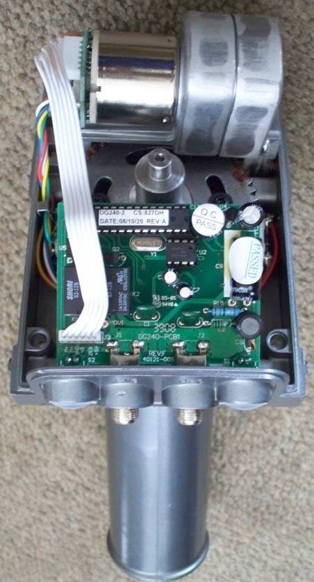
3. Loosen and remove both F-connector hex nuts that mount the circuit board to the case (see "DG-380 Opened" photo). A deep socket worked for me.
4. Disconnect the ribbon cable tying the circuit board to the motor.
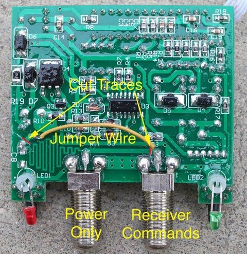
5. Cut the two traces indicated in the "DG-380 Circuit Mod" photo and add the jumper wire shown. You should check that the traces are broken with a meter, but be aware there is a nonconductive coating over the board, so you may have to puncture it or scrape some off to make a valid test.
6. That's it. Reassemble the case.
The photo shows which connector accepts the power for the circuit and the motor (right side when looking from the back when the motor is mounted on the mast) and which connector accepts DisEqC/USALS commands (left side). Note the circuit board photo is from underneath, so don't get crossed up.
Other observations:
When I was testing the mod with my USB box, the receiver would not send commands when directly connected to the motor's command port. I could see this on a scope. It apparently wants a little current draw to operate. I simply hooked a spare DisEqC switch in between the motor and the USB box and all was well. That pretty much mimics how this will be set up in real life.
Because both F-connector ports are used up, the receiver commands have to be split from the line(s) to the LNB outputs. Of course this is exactly what I wanted to do in the first place. There are many ways to do this, but a power inserter, F-tee connector and an optional terminator makes a clean install. I put the tee in-line with the receiver cable, and used a M-M F connector to connect it to the inductor-only side of the power inserter. I put a 75 ohm terminator on the capacitor-only side. The port common to both drives the receiver command line.
First up is the DG-380 HH motor used to drive my 1.2m that has a Invacom QPH-031 LNBF (orthofeed for H&V FSS and L&R DSS). I originally set this up to feed all four inputs of a powered 4x8 switch, which in turn feeds 4x1 DisEqC switches, one for each receiver. The other DisEqC ports went to my other dishes, all of which are motorized. One of my receivers (actually a USB box) was designated as the master to control the motors. The switching matrix for all of the dishes is located a substantial distance from the 1.2m, so when I installed it I used a power inserter and a F tee connector to split off the commands and power for the motor from the LNBs. That meant I had five lines, 4 from the LNBF outputs and 1 to the motor, running between the 1.2m and the switch matrix. This seemed a better approach than running a cable to the motor and back to the switch, or requiring the master to always drive the same band/polarity to move the dish. It also kept the LNB outputs from going through the motor.
Afterwards I had one of my new USB boxes fry while driving the 1.2m, a few minutes after first hooking it up. The manufacturer chalked this up to infant mortality and sent a replacement box, which has worked fine for the past half year. Nevertheless I wasn't thrilled about the load placed on the USB box, given my experience and its relatively lightweight power supply. What I wanted was to have the motor power for the DG-380 separated from the receiver commands. That way I could use a beefy power supply to turn the motor and relieve the receiver from supplying any power at all (the 4x8 switch already provides independent power to the connected LNBs. The receiver switches voltages for H&V and 22 KHz on/off, but at a miniscule current). Because the motor power is a constant 18V (or whatever you want it to be), the drive speed doesn't drop if a V polarization is selected.
The best place to make this mod seemed to be in the DG-380 itself. It already has two connectors, so no external changes would be required. This voids the motor warranty, but I could care less. The mod can probably be done in a similar fashion to other motors. The steps are:
1. Loosen and remove the three screws on the bottom of the motor that hold on the top cover.
2. Remove the top cover.
3. Loosen and remove both F-connector hex nuts that mount the circuit board to the case (see "DG-380 Opened" photo). A deep socket worked for me.
4. Disconnect the ribbon cable tying the circuit board to the motor.
5. Cut the two traces indicated in the "DG-380 Circuit Mod" photo and add the jumper wire shown. You should check that the traces are broken with a meter, but be aware there is a nonconductive coating over the board, so you may have to puncture it or scrape some off to make a valid test.
6. That's it. Reassemble the case.
The photo shows which connector accepts the power for the circuit and the motor (right side when looking from the back when the motor is mounted on the mast) and which connector accepts DisEqC/USALS commands (left side). Note the circuit board photo is from underneath, so don't get crossed up.
Other observations:
When I was testing the mod with my USB box, the receiver would not send commands when directly connected to the motor's command port. I could see this on a scope. It apparently wants a little current draw to operate. I simply hooked a spare DisEqC switch in between the motor and the USB box and all was well. That pretty much mimics how this will be set up in real life.
Because both F-connector ports are used up, the receiver commands have to be split from the line(s) to the LNB outputs. Of course this is exactly what I wanted to do in the first place. There are many ways to do this, but a power inserter, F-tee connector and an optional terminator makes a clean install. I put the tee in-line with the receiver cable, and used a M-M F connector to connect it to the inductor-only side of the power inserter. I put a 75 ohm terminator on the capacitor-only side. The port common to both drives the receiver command line.
8 Replies
·
5023 views

")

Supporting Founder
Lifetime Supporter
Thanks to Fitch Ratings ( who gives the ratings on Credit and debt, as approved by the SEC, so they have accurate numbers) we have the totals.
DIRECTV's video subscriber base is the third-largest traditional multi-channel video programming distributor (MVPD) in the U.S. with about 8.2 million subscribers at the end of 1Q26.
The last time it was reported, it was 8.8M at the end of 2Q25, so only a 600,000 loss for 3 quarters, which is a major improvement, since for many years before that, it was losing 500,000 a quarter, 2 Million a year.
It is now losing less than Dish/Sling combined, I believe the Genre Packs are helping to retain and get subscribers.
8 Replies
·
389 views


Staff member
HERE TO HELP YOU!
Cutting Edge
Sometimes a thread gets so many posts in it that is can cause issues for the server so that why today we introduce The Song Name Game Part 3!
So let the game continue!
The last song was added by Bobby who posted...
One Meat Ball - Andrews Sisters
CONTINUE ON AND HAVE FUN! WELCOME HOME TO SATELLITEGUYS.US!
Here are the original rules for the game as posted by WebbyDude back in 2006. http://www.satelliteguys.us/threads/68645-Song-Name-Game
Just name a song title and the band who performed it. The next person does the same thing, but needs to list a song title or band name which includes a word from the previous entry. Pick songs from any genre.
Example:
Long Live Rock and Roll -- Rainbow
Rainbow in the Dark -- Dio
Another example:
Ride the Lightning -- Metallica
Lightning Strikes -- Ozzy Osbourne
Get it?
An additional note: we all know that song titles, sometimes, use profane words. Because this is a family friendly website it is advised that you clean up that title up a bit. This is accomplished by using something like sh!t instead of the real word. Thanks....
67111 Replies
·
2662411 views
Mexico takes on South Africa to open the World Cup Final (it is called the Final... this just isn't the World Cup Final... Final). The tournament has been plagued with rife malfeasance as FIFA has been committing all sorts of fraud with the ticket sales. Hotel rooms have gone unfilled as the prices to attend a game and stay somewhere are through the roof. I swear this is impacting Mansfield, OH hotel rates which are higher than average for the Indycar race. And there is a broadening VAR presence which will ruin things as nothing worse now when scoring a goal and knowing you can't quite celebrate yet as they check to see if a player was offside by a pixel a half-hour ago.
The Group Stage used to mean something, but now 32 of the 48... yeah, 48 teams are going to the Knockout Round. Getting into the Knockout Round used to be a big deal, even for the US. But now... if you don't lose all of your group stage games, you get to move on. Oi! And this is avoiding all the political stuff!
I have never been so unexcited for a World Cup before. Every game used to matter. But FIFA be darned if they don't try to squeeze out every dime they can out of the players, refs, and fans.
2 Replies
·
55 views
Supporting Founder
Since the Reds have there thread we should too!
Last watched Nine inch Nails
Next 3:10 to Yuma
Last watched Nine inch Nails
Next 3:10 to Yuma
5347 Replies
·
509351 views
Hello everyone, new guy here. I'm trying to solve problem I'm having with Dish bonus view channels. When I'm watching the bonus view channels then I switch back to regular dish channels, after few minutes the screen flips to black and after 30 seconds flips back to regular channels and continues to flip back and forth until I turn off TV. After I wait 30 minutes and turn back on , I can use regular channels again. So, its after I switch from bonus view channels to regular dish channels the problem starts. Been trying to fix this for a month, but no luck
Here what I've done.
i contacted Dish support and they sent me a new Joey3, but no help. Switched to a different HDMI input on TV, no help. Used different HDMI cable , no help. Used different electrical wall plug, no help.
Finally got a Dish tech to check it. He ran all systems check and was OK. Finally he brought in a small TV and plugged in the HDMI out from the Joey to the small TV. He could not get the problem to occur on his small TV, so the new Joey was working OK. So, then the problem must be myTV. He made some phone calls and came back with the answer that there must be a problem with the analog to digital switch in my TV. Has anyone ever heard of a problem like this, or is it time to be looking for a new TV? My tv LG OLED65C8PUA. TV has been trouble free til now. Thanks
7 Replies
·
122 views
Recently came back to DirectTV Satellite service and have two boxes, Gemini and a main HR54.
DirecTV is charging me two "TV access fees" of $10 each, but can only watch TV on the one without the server. Is there anything I can do to fix this?
DirecTV is charging me two "TV access fees" of $10 each, but can only watch TV on the one without the server. Is there anything I can do to fix this?
24 Replies
·
948 views
Pub Member / Supporter
Lifetime Supporter
I feel like this was discussed in another thread, but I can't find it. I have T-Mobile and my last iPhone upgrade was in 2020. I want to get a new iPhone, but what is the best way to go about doing it? Should I order the iPhone from T-Mobile directly, or should I buy from the Apple Store? I feel like there are pros/cons to each option.
2 Replies
·
47 views
I have a Hopper with Sling. (Don't know exact model.) A couple nights ago, I went into the DVR screen, and noted that it was recording three programs. Yet I was able to view live TV (that was not one of the channels being recorded.) Did something change? In the past, it would only let me watch one of the channels being recorded, or any recording in the DVR menu. Maybe it was streaming, although there was no indication of that?
Apologies if this has been covered; I searched and didn't find anything.
Thanks.
Apologies if this has been covered; I searched and didn't find anything.
Thanks.
9 Replies
·
370 views

iJustine
Time for another AWESOME video from iJustine!
View: https://www.youtube.com/shorts/YJjxjYvmQ8s
Direct YouTube Link - Good Bye, Tim! Last WWDC
The official iJustine Website's Website
Buy her book!
View: https://www.youtube.com/shorts/YJjxjYvmQ8s
Direct YouTube Link - Good Bye, Tim! Last WWDC
The official iJustine Website's Website
Buy her book!
0 Replies
·
12 views
Pub Member / Supporter
Cutting Edge
WANTED DirecTV LCC
Anyone have a DirecTV Local Channel Connector that you'd like to get rid of at a reasonable price? DirecTV is currently in a contract dispute with owner of my local ABC affiliate.
12 Replies
·
317 views

