DTV Transmitter woes? (WCCO Minneapolis)

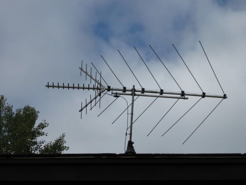
I put up the old antenna and this is what I get:

9/ch9 hd s95/q100%

11/ch11 HD. s98/q100%

22/ch23 hd s51/q98%

23/ch2-3 s53/q100%

29/ch29hd s48/q82%

32/ch4 s68/q100%

34/ch2-1 s51/q98%

35/ch5-1 s73/q100%

45/ch45-1 48/87

The signals around 50% are pretty sketchy

Is that a function of the antenna or the azimuth?

I don't have a pre-amp installed. The signal is split to 4 TVs on a 8way splitter with terminal
resistor caps on the 4 connectors not being used.
 
Last edited:
Also I think I'm getting some splitter loss. Is a distribution amp ok or do I need a preamp?


I guess I should test direct to only one TV


This almost like mine except my uHf elements have a wierd right angle bend and there is a bow-tie loop inside the Yagi

antenna.jpg
 
Last edited:
That antenna looks like its big enough to get the signal. I have a antenna about that size (element wise on the UHF...the VHF is only VHF Hi so there are fewer elements) split to 4 (no amp) and it works fine. All signals in the 90's for signal on the 2 converter boxes, the DTVPal DVR and the HDTV

it sounds like the antenna has to be aimed a little better. I know when I put the antenna up a little bit of azimuth change made a big difference....especially on UHF

I would try it on one TV first to see what kind of signals you get then go from there
 
what does the V-shape do? does it make a wider or tighter signal beam? or is it to take a little less space?

I also noticed the picture has the 300ohm to 75ohm converter at the forward end. Mine is in the middle. That doesn't make any difference does it?

If azimuth is the big deciding factor I'll need to put the rotor back into service. HMMMMMM CLACK HMMMMMMM CLACK HMMMMM CLACK!!!


Here is my actual antenna
myant.th.jpg


and the direct link if you want fine detail
http://img535.imageshack.us/img535/928/myant.jpg
 
Last edited:
Your last element on the left (looking from the rear) is way out of shape, it should be parallel with all the elements in front of it.

Matter of fact you have several elements there that are out of line (3rd from rear on right and 6th from rear on left).

Pull the antenna down and arrange ALL the VHF elements so they are parallel to each other on either side.

It appears that you have the balun attached at the point where the manufacturer designed it to be (I believe I see wing nuts there).
 
I'll get them straightened out

Is being parallel that imperative? Aren't the ones to the right of the ballun for FM and VHf-L ?

I noticed on Iceberg's antenna the vhf radials are at right angles where mine is in that vee formation. Whats the difference
 
From hdtvprimer.com/ANTENNAS/types.html with regard to log-periodic dipole array (LPDA) antennas:

TV LPDAs come in two types: straight and Vee. The Vee type (LPVA) has a very slightly higher gain for channels 7-13. But this author often favors the straight type since it has nulls 90 [degrees] to each side that can be used to cancel out interference.
hdtvprimer.com is a good source of info that I use quite a lot.

Is that a RadioShack VU-190 antenna? It looks a lot like one.

DRCars[FONT=&quot]
[/FONT]
 

Users Who Are Viewing This Thread (Total: 0, Members: 0, Guests: 0)

Who Read This Thread (Total Members: 1)