I'm doing a school project that considers the path and frequency dependence of signal fading on satellite links, and I was wondering if I could get some help identifying the operating frequencies and orbital positions of the signals I'm seeing, or just some guidance as to where I can identify the transponders I'm looking at.
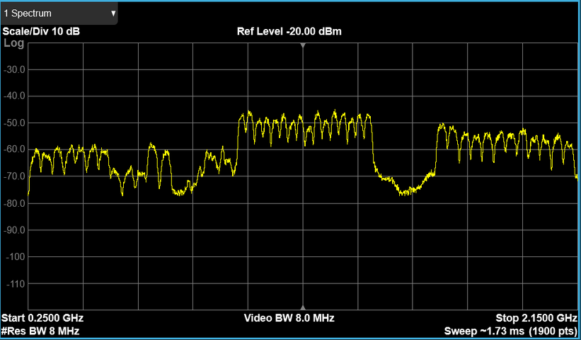
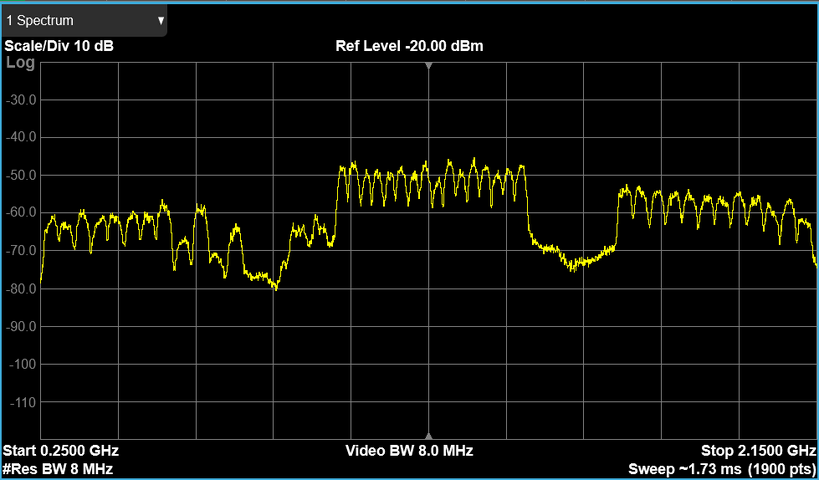
Here are screenshots from a spectrum analyzer of signals pulled off of a multiswitch. Signals are received by an SL3 (non-SWiM) LNB and the signals are separated using a bias tee placed between the multiswitch and the LNB. I have downloaded some of the documentation from the 'Directv Transponder Map Data' thread, but I haven't been able to piece the information together yet.
18V, 22KHz OFF:
99b Ka-Low, 101 Ku, 99a Ka-High

18V, 22kHz ON:
103b Ka-Low, 110/119 Ku, 103a Ka-high

I am confused by the 20MS/s signals in the Ku band slots on the 103/110/119 outputs. My understanding is that satellites 110/119 shouldn't be received by the SL3, and 110 isn't transmitting anymore. If that's the case, where are the signals coming from? I'm assuming these 20MS/s signals are Ku and transmitted from 103, but I'm unaware of what the Ku transponders could be. I checked in the 'DirecTV Domestic Bands Plans 210724' document, but the only Ku stuff I see there is for 101 and 119. Could these signals be the 'D15 Ku Band for use at 101W' listed in the 'Domestic Satellite Transponders 220519' document? I am aware that there is a Ku footprint map for D15 Ku-US at 103 in the 'Interactive Beam Footprint Library' thread.
How can I piece together the transponders/frequencies for all of these signals? I was previously consulting this diagram from Solid Signal Blog and information on LyngSat, but I've gotten a bit confused as of late.

Another thing worth mentioning - I noticed today the multiswitch is not outputting the 13V signal. I am okay with only looking at the LHCP signals, but I am unsure if this would affect the 18V lines' signals.
Here are screenshots from a spectrum analyzer of signals pulled off of a multiswitch. Signals are received by an SL3 (non-SWiM) LNB and the signals are separated using a bias tee placed between the multiswitch and the LNB. I have downloaded some of the documentation from the 'Directv Transponder Map Data' thread, but I haven't been able to piece the information together yet.
18V, 22KHz OFF:
99b Ka-Low, 101 Ku, 99a Ka-High
18V, 22kHz ON:
103b Ka-Low, 110/119 Ku, 103a Ka-high
I am confused by the 20MS/s signals in the Ku band slots on the 103/110/119 outputs. My understanding is that satellites 110/119 shouldn't be received by the SL3, and 110 isn't transmitting anymore. If that's the case, where are the signals coming from? I'm assuming these 20MS/s signals are Ku and transmitted from 103, but I'm unaware of what the Ku transponders could be. I checked in the 'DirecTV Domestic Bands Plans 210724' document, but the only Ku stuff I see there is for 101 and 119. Could these signals be the 'D15 Ku Band for use at 101W' listed in the 'Domestic Satellite Transponders 220519' document? I am aware that there is a Ku footprint map for D15 Ku-US at 103 in the 'Interactive Beam Footprint Library' thread.
How can I piece together the transponders/frequencies for all of these signals? I was previously consulting this diagram from Solid Signal Blog and information on LyngSat, but I've gotten a bit confused as of late.
Another thing worth mentioning - I noticed today the multiswitch is not outputting the 13V signal. I am okay with only looking at the LHCP signals, but I am unsure if this would affect the 18V lines' signals.


