Hi,
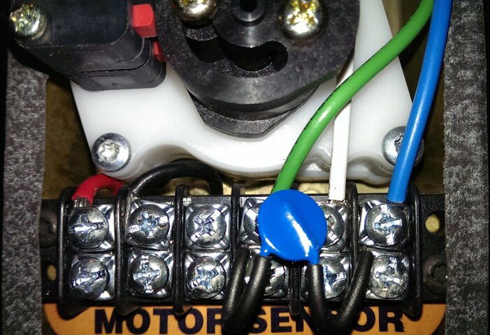
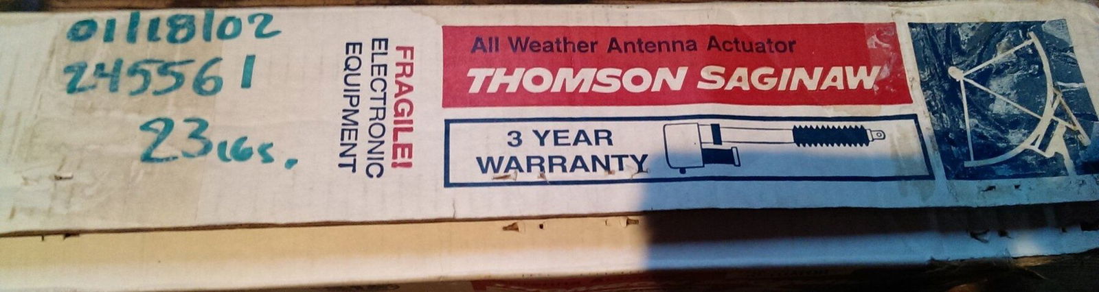
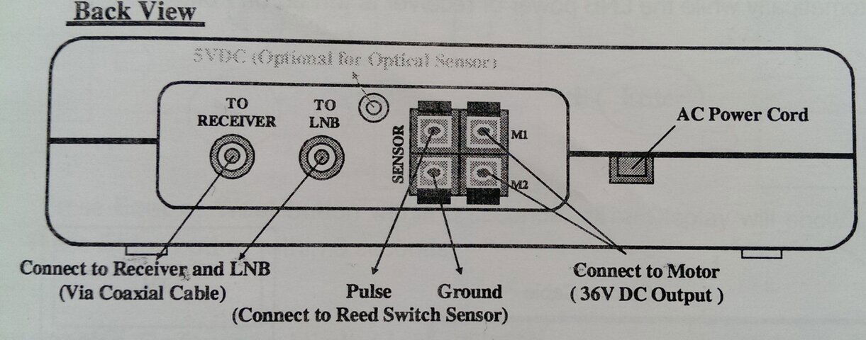
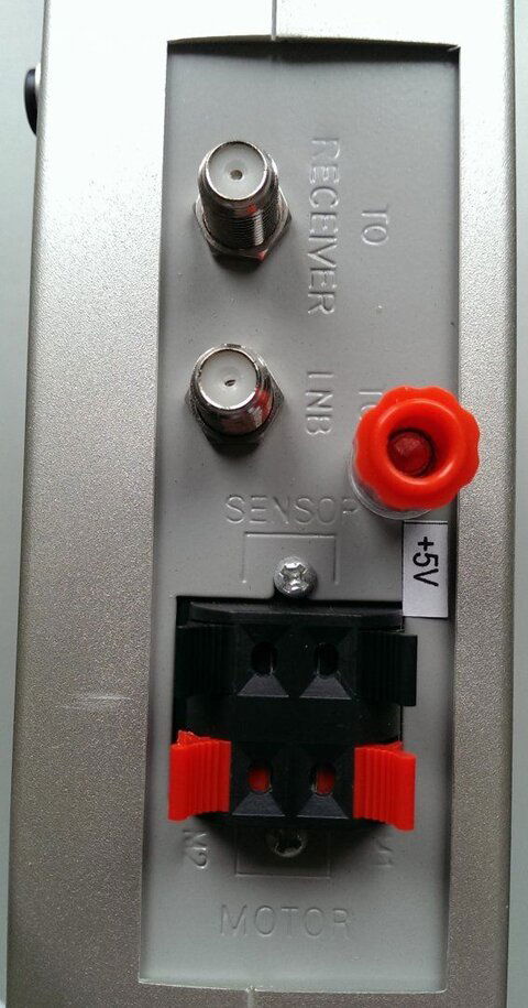
I came across some new (old stock) 36" Thompron Saginaw actuators but there were no wiring details included in the box or inside the removable wiring head cover. Would anyone please be able to advise me of the correct wiring of these actuators to a v-box or an old satellite receiver with internal positioner. I have v-boxes and satellite receiver/positioners with the +5V connector if that is required? I have attached some pictures of the wiring layout and the original box.
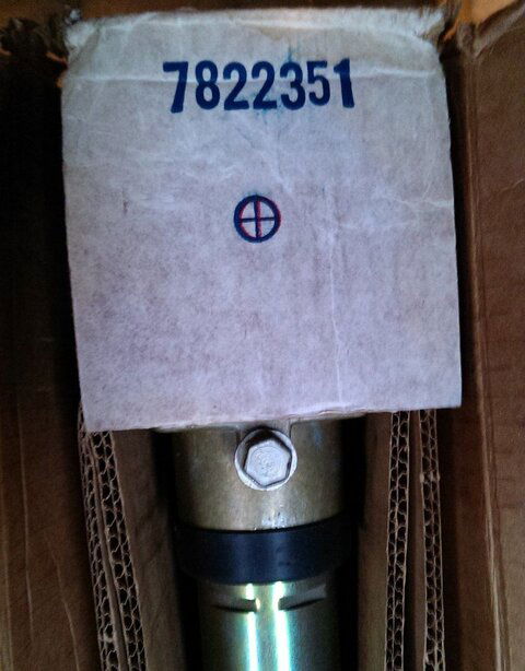
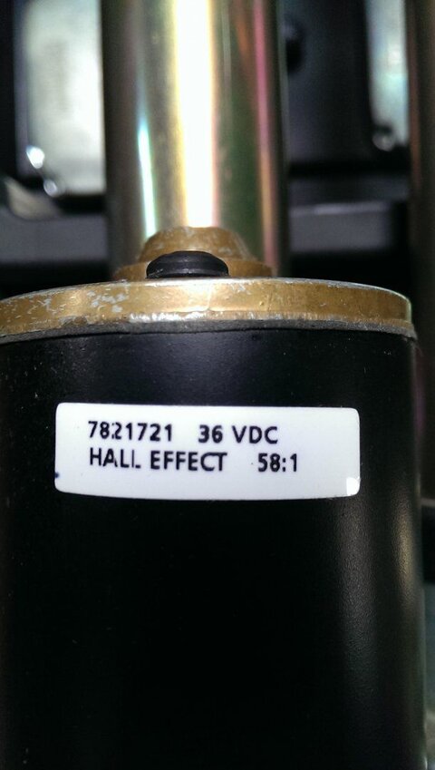
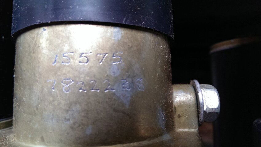
One of the boxes has the number 7822351 on a cardboard flap inside the box, another box has the number 7821072 written on the end of the box as a product/part number if that helps with identification for the wiring? I think there might be a few variants of model so if anyone has the identical model to refer to that would be great.
Any help most appreciated.
I came across some new (old stock) 36" Thompron Saginaw actuators but there were no wiring details included in the box or inside the removable wiring head cover. Would anyone please be able to advise me of the correct wiring of these actuators to a v-box or an old satellite receiver with internal positioner. I have v-boxes and satellite receiver/positioners with the +5V connector if that is required? I have attached some pictures of the wiring layout and the original box.
One of the boxes has the number 7822351 on a cardboard flap inside the box, another box has the number 7821072 written on the end of the box as a product/part number if that helps with identification for the wiring? I think there might be a few variants of model so if anyone has the identical model to refer to that would be great.
Any help most appreciated.