How does your switchbox look like?

Status
Please reply by conversation.
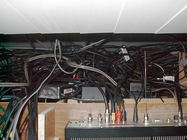
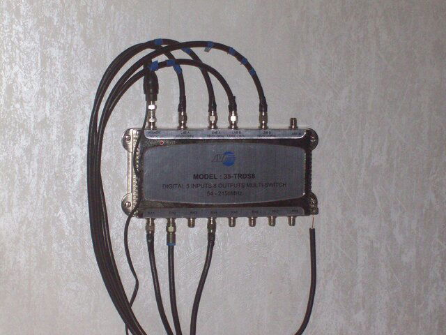
Nice job mounting the box with the 80-20

Hello "Mr. Red-Green" Dodge,

How's Harold? ;) I see you caught that construction material for my box mounting. I use it a lot! 80-20 is great for all sorts of things. The industrial erector set.

I did make an error, though. The electrical enclosure box isn't mfg by Thompson, but by Hoffman.

You have a good eye.

RADAR
 
Last edited:
Could you elaborate a bit on having taps for each LNB output. What they're for, and how do you pick a tap to put on a particular LNB output? What tap makes and models you can suggest?

I have taps at the dish for each LNB output, for tuning and troubleshooting purposes. With 44 LNB outputs, lots of dishes and an evil mind, there is always something to mess around with or improve. By virtue of a tap, I can connect my signal meter or other test equipment with one connection without having to disconnect any cables or disturbing the signal and power paths. Saves a lot of time when the weather is horrible and keeps me honest because checking all the LNB outputs is easy. When I get around to documenting my system, I'll include all the gory details like this.

Sadoun used to have some decent Eagle Aspen taps of various flavors and I stocked up on a ton of them. But they're supposedly all gone, and I ordered some Sonora devices a few days ago because I'm about to run out. I hope they work at least as well.
 
Anyone else wants to share your switchboard photos? So far we have just a few switch matrix examples in this thread, but need a lot more for everyone being able to see proven solutions, listen to new ideas, and figure out how to improve his or her signal reception experience with minimum investment. From what I read so far here, by using low loss correctly sequenced switches and diplexers, by powering LNBs and Motors separately from signal lines, and with proper signal amplification from each LNB, sat signal levels can be raised, and extra noise and equipment overload eliminated. Motors will turn faster, and channels switch in a blink of an eye, reception of weak signals can improve greatly. Apparently, a lot more depends on our attentive to details switch matrix than one could ever imaging. Lets allow everyone's accomplishments in this field to benefit all. :)
 
Want to know, how your switchboard should NOT look like? The guy who posted it said to pay big bucks to a "pro installer" to do it like this. :D 
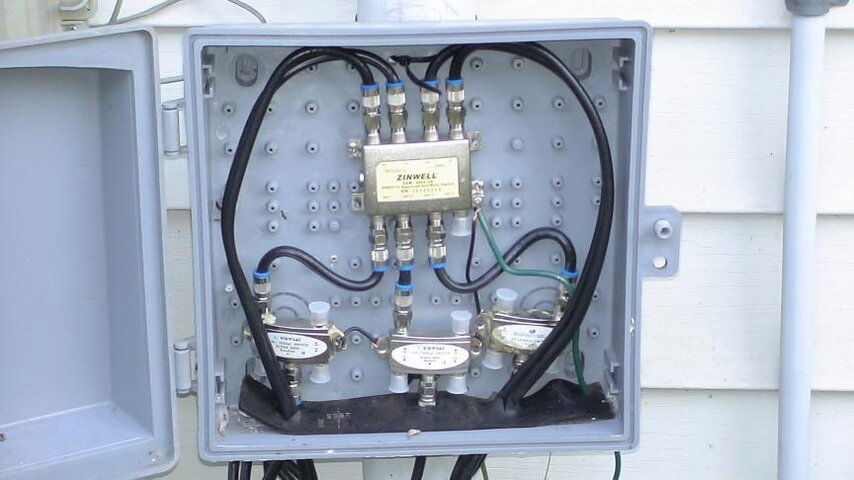
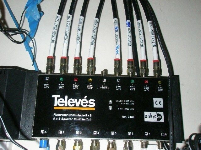
In contrast, the next switchbox is a good candidate for a proper simple switchbox example.

Low current wiring is particularly susceptible to "current ground loops" introducing noise into the system, which components are grounded at distant points from each other. Want to learn how to ground your system properly to eliminate such noise and also prevent high current caused equipment damage? Try attaching all your coax cables to a common Ground Point outside the house near your Service Entry Point with closely positioned to each other grounding blocks, making coax drip loops if required to keep water out. Run grounding wire from each grounding block to the central building grounding or service pole. See attached "Cable Grounding" reference pics.

Do you suspect your DiSEqC Switch may be defective or damaged? The attached file I found describes how to test a DiSEqC Switch ports one by one at home. Its not the best manual, I've ever seen, but certainly better than nothing, especially if you don't have specialized equipment at hand. You're welcome to post a better manual on this subject, if available. ;)
 

Attachments

  • Bad Switchboard.jpg
    Bad Switchboard.jpg
    80.6 KB · Views: 311
  • Testing DiSEqC Switches.pdf
    99.8 KB · Views: 192
  • Cable Grounding 2.gif
    Cable Grounding 2.gif
    27.2 KB · Views: 301
  • Good Switchbox.jpg
    Good Switchbox.jpg
    49.9 KB · Views: 439
  • Cable Grounding 1.gif
    Cable Grounding 1.gif
    26.2 KB · Views: 290
Last edited:
B/S:

In the switch test PDF, the author says "diseqc or multiswitch", which is suspect enough.
Then shows what looks like a DishNetwork SW21.

Whatever he's testing may catch some bad switches, but it's certainly not a test I'd waste time performing, nor relying on.

well considering that is a hacker he gets what he deserves ;)
That is certainly true, if the dish photo is his!
 
In the switch test PDF, the author says "diseqc or multiswitch", which is suspect enough.
Then shows what looks like a DishNetwork SW21.

Whatever he's testing may catch some bad switches, but it's certainly not a test I'd waste time performing, nor relying on.


Anole,

On another note: "If [open] the switch will pass the voltage thru to the meter, and you will achieve a reading on the meter."

I must have been sleeping in my basic electronics class that day.

Awh heck, I know what the author meant, but it bugs me.

RADAR
 
Anyone want to take on tracing my setup

Here's a picture behiind my rack. Total rats nest but hey it works :)

Any takers wanting to trace it? I have a good schematic of it all in my head.
 

Attachments

  • IM005193.JPG
    IM005193.JPG
    340.8 KB · Views: 254
tvropro

What's that black piece of equipment shown on the front plan for, and how do you control it from your house living areas? It looks like a pretty big switchboard mounted on the wall behind it. :)
 
tvropro

What's that black piece of equipment shown on the front plan for, and how do you control it from your house living areas? It looks like a pretty big switchboard mounted on the wall behind it. :)

Are you talking about the unit in front of the picture? Thats my 922.

Here is a quick shot I just took of my rack (excuse the slightly poor picture quality)
 

Attachments

  • RACK.jpg
    RACK.jpg
    202.5 KB · Views: 259
Below are offered typical examples of switches and switch matrices to extend the range of solutions covered in the forum's basic Switch FAQ. It would be nice to have more info added here about these switching solutions. While they are self-explanatory, anyone is welcome to post solid content links or more verbiage and extra schematics addressing the following:

- How a large Multiswitch works from schematics standpoint - the one (with DiSEqC switch integrated?) having more than 6 Out ports to hook up LNBs?

- How a Cascading Multiswitch works? What they're for, and how to setup correctly? In what kind of systems commonly used Cascading Multiswitches are preferred to a larger multi-LBN port Multiswitch?

- How to correctly combine commonly used Multiswitches with high frequency splitters connected btw them and (regular or bandstacked) LNBs? Advantages & Drawbacks? Splitter makes and models? Setup sequence details...

- In what multi-receiver installations a cascaded mix of DiSEqC 4x1 and 22 KHz switches or splitters would be preferred to a Multiswitch matrix?

- Under what conditions using 8x1 DiSEqC Switches in a Single or Multi-Receiver switch matrices becomes more rational than other choices?
 

Attachments

  • Televes 9x8 DiSEqC 2.0 Multiswitch.jpg
    Televes 9x8 DiSEqC 2.0 Multiswitch.jpg
    71.1 KB · Views: 1,234
  • Cascading Multiswitches.jpg
    Cascading Multiswitches.jpg
    38.2 KB · Views: 638
  • Spaun 16x6 DiSEqC Multiswitch.jpg
    Spaun 16x6 DiSEqC Multiswitch.jpg
    54 KB · Views: 308
  • Splitters with Multiswitch.jpg
    Splitters with Multiswitch.jpg
    13.5 KB · Views: 295
  • DiSEqC 4x1 and 22 KHz 2 STB Switch.jpg
    DiSEqC 4x1 and 22 KHz 2 STB Switch.jpg
    43.9 KB · Views: 725
  • 8x1 Switches in Multi-Receiver Setup.jpg
    8x1 Switches in Multi-Receiver Setup.jpg
    57.2 KB · Views: 357
Last edited:
No
I Sure Hope You Never have Any Problems back There :eek:

No Problem :D I change things all the time. Being the one that put it all together I understand what goes where. The only problem is untangling the wires. :eek:

Long time ago I had everything neat with tie wraps, wire loom covers etc. I found out that was a bigger headache when I wanted to change things. Being accessible (even though a rats nest) when something needs to be changed all I need to do is disconnect and connect as needed. No playing around with the neat route. I swap stuff often.

Works for me :up :D
 
Anyone can post solid content links or explanations and schematics addressing the following:
I dont post links. I usually post what I know :)

- How a large Multiswitch works from schematics standpoint - the one (with DiSEqC switch integrated?) having more than 6 Out ports to hook up LNBs?
biggest multiswitch I have seen is a 17x16 which unless you have bandstacked LNB's is a 8x16 multiswitch. It would work with Diseqc 1.1 protocol (easiest) or Diseqc 1.2 which is a little more difficult.

- How a Cascading Multiswitch works? What they're for, and how to setup correctly? In what kind of systems commonly used Cascading Multiswitches are preferred to a larger multi-LBN port Multiswitch?
very rarely would you cascade multiswitches in a FTA world unless you have some laying around. Most of the time just get a bigger multiswitch. The original reason for cascading switches was for DIsh/Direct/Bell/Starchoice.

Technically you could cascade it for FTA by taking a 3x4 multiswitch and hooking 2 of the outputs from one switch to the inputs of another to give you 6 outputs

- How to correctly combine commonly used Multiswitches with high frequency splitters connected btw them and (regular or bandstacked) LNBs? Advantages & Drawbacks? Splitter makes and models?
you already posted a pic of one. :)

- In what multi-receiver installations a cascaded mix of DiSEqC 4x1 and 22 KHz switches or splitter would be preferred to a Multiswitch matrix?
multiswitch and diseqcs....that is the easiest. Anole already posted pics of those setups

- Under what conditions using 8x1 DiSEqC Switches in a Single or Multi-Receiver installations becomes more rational than other choices?

again we've already been down this road. Easiest in a single is if the receiver supports Diseqc 1.1 Then you dont need 2 4x1 switches and a 22k switch for 8 LNB's
For multi receivers you still need multiswitches
 
This is my old switchbox.
Thanks Iceberg.

Nice looking box, Radar! Classic low cost setup, just like on one of these schematics. What are the advantages of using 80-20 aluminum rails to mount it on the wall? ;) How did you ground your cables - a photo would be nice?
 
Zamar > That Televes switch is designed for Europe/ Mid East and requires the special Invacom quatro QTH031, QTF031 universal or similar. I guess you could put standard LNBs on ports 3,4,8,9 as they would ignore the 22HZ signal.
It is expensive for a 2 Sat and OTA switch
Spaun are the most popular by far in Europe
 
Zamar > Whilst the codes are clear they appear to have been written for Cband, DN annd DTV where the dish itself has a direct connection to the coax shield.
However with FTA where this is rarely the case, as LNBs and their holders are plastic. I think the European method of additionally grounding the dishes themselves locally to be more appropriate. Since there is then no ground connection to the house ground there would be no ground looping involved.

Perhaps like European codes this is covered in another unrelated chapter.

Actually the idea of the coax doubling as part of the lightning conductor route is a alien to me.
 
Are you talking about the unit in front of the picture? Thats my 922.

Here is a quick shot I just took of my rack (excuse the slightly poor picture quality)

What memories this picture brought to me. I also had that plastic satellite dish LCD clock back in the 80's. I believe I bought it on Green Sheet.
 
What memories this picture brought to me. I also had that plastic satellite dish LCD clock back in the 80's. I believe I bought it on Green Sheet.

I got mine free with my subscription to the old STV guide magazine. The clock died but I always had the dish up there :) I was thinking of putting a led in the feedhorn and have it turn on with my tv :)
 
This is my setup , as for the Ku system goes . The reason why i went with this configuration is because i have several televisions thru the house ( kitchen ,one in each living room and one in bed room) I am able to utilize both linear and cicular ( not much there but Nasa) The reciever is a Fortecstar dynamic , lnb quad polar , DG 380 motor mounted to a 31" fortec switch is a 35-TRDS8. I am able to use both DiSeqc and USUALS controls for the motor , but i prefer USUALS . The switch is mounted in the house only 20' from the dish and if mnt. is needed it's much esiar to get at in the winter months.
 

Attachments

  • confif..JPG
    confif..JPG
    74.8 KB · Views: 252
  • switch.JPG
    switch.JPG
    851.3 KB · Views: 235
Last edited:
Status
Please reply by conversation.

Users Who Are Viewing This Thread (Total: 0, Members: 0, Guests: 0)

Who Read This Thread (Total Members: 2)