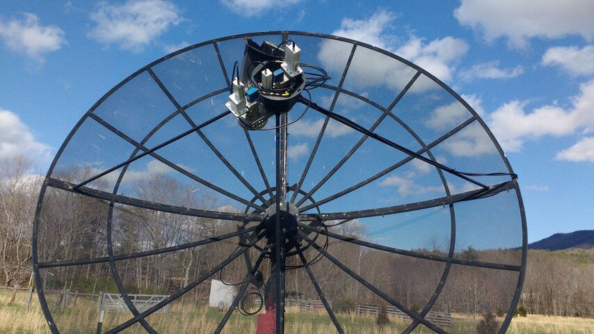
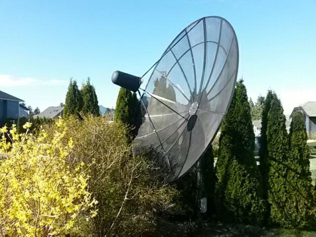
My Sunday project was to add another feed to my 10-foot Unimesh, for circular polarization reception. The recipe called for an old scalar ring and single-band polarotor, LNB, junk metal brackets, and a cheesy plastic cutting board. It was a success.
Quick look at the photos and diagram attached describe the thousand words below.
A quote from a thread on here a while back inspired me. Someone discussed multi-feed arrangements, and then posed the question, "wonder if I could do that on my dish that tracks the arc". Someone responded, "why would you do that?!" -- makes sense, you do multi-feed arrangements so you don't HAVE to turn the antenna.
BUT, let's say you want to be able to switch from linear polarities to circular polarities on the fly, without having to go out to the antenna and swap your feeds out or jam a dielectric plate in the feed?
The prime feed is a C/Ku polarotor, with Norsat LNBs. The antenna runs a VonWiess motor, and an ASC-1 controller drives the motor and the servo.
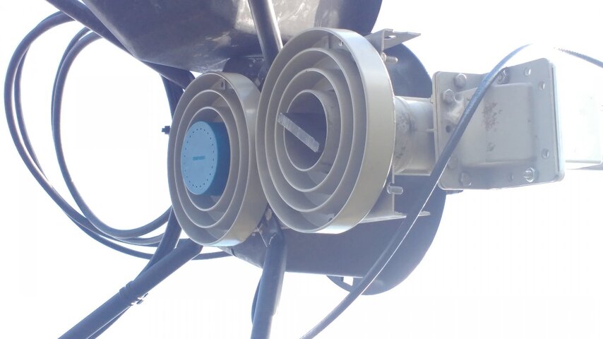
Adding the second feed was simple; I opted for a second full scalar ring to start. It was placed right up against the prime feed. I had pre-perforated steel angle brackets laying around that I cut to support the new feed. The prime feed ring was removed from the support arms of the reflector, those bolts then run through the brackets, and the feed support arms were placed on top of the brackets. (All this done wit 20MPH wind gusts, on a ladder! That, indeed, resulted in profanity!).
This arangement set the phase center of the feed off from the prime feed a good 8 inches or so. Since the target C-pol birds were further EAST, I placed the feed to the WEST of my prime feed.
Switching between my C/Ku LNBs has always been achieved with a 22kHz tone switch, 2-in/1-out. This had to scale up to a real DiSEqC switch. I had a 4-port Pansat switch, which didn't seem to want to work behind the ASC-1. I had another 8-port on hand that did work. So this was placed in the prime feed's radome.
Control of the offset feed's polarity runs in parallel with the prime. Two parallel motors seems to work flawlessly with the ASC-1. An old California Microwave LNB I rescued from somewhere ended up on the new offset feed.
Tested the new offset feed with linear polarity first. It was hearing birds OK, at about 70% magnitude (more than I expected) relative to the prime feed, and about 10 degrees further East-looking. This result was after some peaking was done on the angle at which the feed looked back into the reflector, and on the f/d plunge. The prime feed was also re-peaked, and each checked again to ensure accurate reference.
Next, a cheap cutting board from a discount chain box store was sacrificed -- a small square was cut out that would fit down the throat of the polarotor feed -- maybe 2-1/4" square or so. The measurement was eyeballed, then cut on the outside line, then edge-shaved with a utility knife for a snug fit. There were no guide rails in this feed for such a plate. Those rails exist in my prime feed, but the Ku-band corner reflector obstructs any chance of a dielectric plate being inserted there.
Side bar: So, the whole "dielectric plate" idea is to add a material with a slower wave propagation constant relative to air, which "de-polarizes" or "linearizes" (I like the latter term better!) a circularly polarized wave so it can be received with a linear polarity instrument. This method has a penalty of no less than -3dB loss over a stepped waveguide or phased probe array -- but has the advantage of being real cheap and easy. A 3dB hit was therefore deemed tolerable, even on top of the offset feed loss, on account of cost, simplicity, and feed structure mass, and resultant feed blockage. Plates are sold online for cheap -- Teflon-like materials and fiberglass seem to be the most popular. But I wondered if real cheap cutting board plastic (not even close to Teflon) would work.
The plate is inserted at a 45 degree angle relative to the linear feed positions (H/V). So observing where my ASC-1 placed the feed probe at max H-pol signal, the plate I cut was jammed -- then hammered gently -- in place at an eyeballed ~45 degrees. Close enough.
Earlier in the week, I'd steered over to SES14 and SES6 (near the extreme travel for my west-mounted screwjack polar mount) to see what happens with C-pol on linear feeds. Confirmed, as I suspected, that some transponders could be heard with a linear feed -- and indeed H/V didn't make a difference, nor did Left-hand/Right-hand! So long as that transponder's passband had NO signals in the opposite polarity, we were OK. But this is a trite handful of transponders. Data point collected!
Now, with sun set, chilly night air settling, I settled on the couch to find those birds again, this time on the offset feed with the linearizing plate. Showed up right where I expected them to from calculated position counter clicks! A few manual scans with my Vu+ Uno 4kSE revealed more transponders! And indeed, changing polarity on this linearized feed from H/V drastically changed SNR on those transponders who were previously uncopiable!! I hooked up my old AzBox to blind scan these birds and reveal more stuff!!
This is SOOOO COOL!
A note: Polarity commands on the Vu+ and the AzBox for H/V /can/ operate +13/+18V; and ASC-1 understand what to do with this. Vu+ has polarity descriptors for transponders that call out Left/Right hand CP. However, my box doesn't seem to change its output LNB voltage to instruct ASC-1 what to do. For now, I'm using the linear term on the box (H/V, for R/L, respectively).
VY 73 DE KF4YLM
Quick look at the photos and diagram attached describe the thousand words below.
A quote from a thread on here a while back inspired me. Someone discussed multi-feed arrangements, and then posed the question, "wonder if I could do that on my dish that tracks the arc". Someone responded, "why would you do that?!" -- makes sense, you do multi-feed arrangements so you don't HAVE to turn the antenna.
BUT, let's say you want to be able to switch from linear polarities to circular polarities on the fly, without having to go out to the antenna and swap your feeds out or jam a dielectric plate in the feed?
The prime feed is a C/Ku polarotor, with Norsat LNBs. The antenna runs a VonWiess motor, and an ASC-1 controller drives the motor and the servo.
Adding the second feed was simple; I opted for a second full scalar ring to start. It was placed right up against the prime feed. I had pre-perforated steel angle brackets laying around that I cut to support the new feed. The prime feed ring was removed from the support arms of the reflector, those bolts then run through the brackets, and the feed support arms were placed on top of the brackets. (All this done wit 20MPH wind gusts, on a ladder! That, indeed, resulted in profanity!).
This arangement set the phase center of the feed off from the prime feed a good 8 inches or so. Since the target C-pol birds were further EAST, I placed the feed to the WEST of my prime feed.
Switching between my C/Ku LNBs has always been achieved with a 22kHz tone switch, 2-in/1-out. This had to scale up to a real DiSEqC switch. I had a 4-port Pansat switch, which didn't seem to want to work behind the ASC-1. I had another 8-port on hand that did work. So this was placed in the prime feed's radome.
Control of the offset feed's polarity runs in parallel with the prime. Two parallel motors seems to work flawlessly with the ASC-1. An old California Microwave LNB I rescued from somewhere ended up on the new offset feed.
Tested the new offset feed with linear polarity first. It was hearing birds OK, at about 70% magnitude (more than I expected) relative to the prime feed, and about 10 degrees further East-looking. This result was after some peaking was done on the angle at which the feed looked back into the reflector, and on the f/d plunge. The prime feed was also re-peaked, and each checked again to ensure accurate reference.
Next, a cheap cutting board from a discount chain box store was sacrificed -- a small square was cut out that would fit down the throat of the polarotor feed -- maybe 2-1/4" square or so. The measurement was eyeballed, then cut on the outside line, then edge-shaved with a utility knife for a snug fit. There were no guide rails in this feed for such a plate. Those rails exist in my prime feed, but the Ku-band corner reflector obstructs any chance of a dielectric plate being inserted there.
Side bar: So, the whole "dielectric plate" idea is to add a material with a slower wave propagation constant relative to air, which "de-polarizes" or "linearizes" (I like the latter term better!) a circularly polarized wave so it can be received with a linear polarity instrument. This method has a penalty of no less than -3dB loss over a stepped waveguide or phased probe array -- but has the advantage of being real cheap and easy. A 3dB hit was therefore deemed tolerable, even on top of the offset feed loss, on account of cost, simplicity, and feed structure mass, and resultant feed blockage. Plates are sold online for cheap -- Teflon-like materials and fiberglass seem to be the most popular. But I wondered if real cheap cutting board plastic (not even close to Teflon) would work.
The plate is inserted at a 45 degree angle relative to the linear feed positions (H/V). So observing where my ASC-1 placed the feed probe at max H-pol signal, the plate I cut was jammed -- then hammered gently -- in place at an eyeballed ~45 degrees. Close enough.
Earlier in the week, I'd steered over to SES14 and SES6 (near the extreme travel for my west-mounted screwjack polar mount) to see what happens with C-pol on linear feeds. Confirmed, as I suspected, that some transponders could be heard with a linear feed -- and indeed H/V didn't make a difference, nor did Left-hand/Right-hand! So long as that transponder's passband had NO signals in the opposite polarity, we were OK. But this is a trite handful of transponders. Data point collected!
Now, with sun set, chilly night air settling, I settled on the couch to find those birds again, this time on the offset feed with the linearizing plate. Showed up right where I expected them to from calculated position counter clicks! A few manual scans with my Vu+ Uno 4kSE revealed more transponders! And indeed, changing polarity on this linearized feed from H/V drastically changed SNR on those transponders who were previously uncopiable!! I hooked up my old AzBox to blind scan these birds and reveal more stuff!!
This is SOOOO COOL!
A note: Polarity commands on the Vu+ and the AzBox for H/V /can/ operate +13/+18V; and ASC-1 understand what to do with this. Vu+ has polarity descriptors for transponders that call out Left/Right hand CP. However, my box doesn't seem to change its output LNB voltage to instruct ASC-1 what to do. For now, I'm using the linear term on the box (H/V, for R/L, respectively).
VY 73 DE KF4YLM