LNB Voltage controlling Analog Polarity (SERVO)

Status
Please reply by conversation.

FaT Air

HOA Free Zone
Original poster
Feb 27, 2010
6,668
916
97W 48N
For those using an analog receiver to control the feed servo for polarity control.
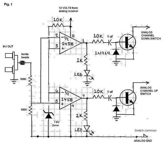
Here's something I've been brainstorming. Programmed with a soldering iron.
A Work in progress. Anyone have any comment?

Theory:
LNB voltage is divided by equal resistances to equal 1/2 the LNB voltage. This will result in approx 6.5 and 9 volts applied to the comparators.
The other input to the comparators is clamped to 7.5 to 8 volts by a zener. This will result in one or the other comparator output being high.
This will turn on the corosponding LED and momentarily cause the associated transistor to conduct as the capacitor in its base lead charges.
The open collector outputs will appear as a momentary short to ground.
The reversed diode, base to emitter, discharges the capacitor when the comparator output goes low. This should ensure switching at rapid rates of channel change.

Will require further output circuitry if the channel UP / DOWN of the analog receiver is matrixed, and does not use ground as common.
 

Attachments

  • ScanImage001.jpg
    ScanImage001.jpg
    70.5 KB · Views: 273
never mind!

last edit:
Okay, I finally got your point. :rolleyes:
Sorry for being slow.
Interesting idea - use the analog receiver to make the pulses to the servo! - :D
Very clever 'n creative - :up


just disregard the previous comments below:


If you are controlling the servo, you need a pulse stream of the correct width (and some modest rate) to select V vs H.

edit:
We had a discussion of this a while back. Might be good to dig it up for ideas.
There's a sticky in the C-band section, but it is... uhhh... doesn't quite get there.
One of the members build a prototype box last year that did the job with a little single chip microcontroller.
That thread had a number of additional good ideas.
 
Last edited:
Yeah, all this circuit does is change the channel on the analog receiver up and down. Even and Odd channels are opposite polarity. So changing polarity on the STB would change the polarity at the feed as the circuit has changed the channel on the analog. `Some newer receivers do not allow scanning one polarity at a time (SSO) so you end up doing two scans and getting 2 listings for a channel. This would eliminate this.
 
Two more thoughts...
- you could get to a condition where you were out of sync; would be cool to think of a way to auto-correct that.
- if the receiver buttons were not relative to ground (part of a matrix, as you mentioned), you could easily drive little reed relays with your transistors; the relay contacts would float and 'push your buttons'. ;)
 
you could get to a condition where you were out of sync; would be cool to think of a way to auto-correct that.
that would be way cool, suggestions?? I don't think there is an easy solution. Reason to have the LEDs to reference as one should be on with an even channel, the other on with odd channel. Using sensitive reed relays was what I was thinking, for matrixed switches. I have ordered the parts I don't have in the bin. Hopefully, will have something "on the bread board" in the not too distant future.
 
When I brainstorm with friends on problems, we pitch all sorts of ideas, no matter how silly they sound.
What we've found is, my stupid idea may just be the basis for your brilliant insight!
So, here's what I came up with while out driving tonight:
- some electronics that monitor the pulse width the receiver is sending.... maybe with a CMOS one-shot.
- hot-glue a magnet and reed to the servo motor so we know where it's aimed...
- say, doesn't your receiver have LEDs on the front panel that says Odd/Even channel? If so, drive a reed relay with one!

Another thing I noticed, is that you have no hysteresis in your voltage detection circuit.
I'd put some in, just to improve the design.

And the last thought is this: maybe it's time to take a whole new approach?
If and when you want to chat, I'll be around.

A well integrated design with a motor controller, could be killer... and just a minor addition to the existing microprocessor.
We did suggest something like this for the next version of Sadoun's Gbox, and he seemed to like it, but with the poor economy, nothing ever happened.
With a knowledge of which satellite you were on, we could tune the servo to a custom/optimum position.
But even a stand-alone unit with a micro, could be outstanding, too! ;)
(see Equant's design, mentioned in this thread)
 
This project is only aimed at those that use an analog to move the dish AND run the polarity servo. If you're G or V box equipped, analog ONLY operating the polarity servo, I suggest the Budfoot design,
I thought hysteresis would have had to be added if the monitored voltage were slow to rise or fall, but since it's two known levels, and should "slam" from one to the other, it shouldn't be a problem. Will find out easy enough, when it's bread boarded.
Thought also of a one shot to sync the pulse width of the analogs servo signal with the V/H command from the STB. Just having a brain fart to the logic math. Everything I have penciled, so far, would sync OK, then get in the way during normal operation. (CMOS Schmitt triggers have been ordered)
I followed Equant's thread and also looked at Budfoot's design, and bookmarked associated webpage. Just can't see the addition of another piece of equipment just to move the servo when that is already available in the analog receiver, that's moving the BUD, and in some setups, also running the servo manually. I am pretty sure most, if not all, analog receivers will also store servo position per satellite. So we'd be "one Up" on the designs of Equant and Budfoot. Should be small enough to put inside the analog receiver and cost only around 10 to 15 bucks.
Since many are using an analog to move the BUD and run the servo manually, maybe automatic sync isn't worth the headache. Just turn it all on, manually sync, and you're off and running?? (KISS Principle)
I was hoping for the "New" Gbox with servo control incorporated, and thought the tone of the threads was very positive. Hopes were dashed when nothing materialized.
We'll see what works, (or doesn't) when my parts arrive, and some spare time is available.
EDIT- Sync may be advantageous, Just remembered, I think most analog receivers remember "last channel"
 
Last edited:
Status
Please reply by conversation.

Users Who Are Viewing This Thread (Total: 0, Members: 0, Guests: 0)

Who Read This Thread (Total Members: 1)

Latest posts

Top