Sonicview 8000 HD mods

Status
Please reply by conversation.

zamar23

SatelliteGuys Pro
Original poster
Feb 5, 2009
1,204
1
Mid West
I started this thread, as more and more used out of warranty SV HD receivers are getting sold for a lot less on EBay, Craiglist and such, and new owners can do easy mods described below to expand the STBs legit functionality and extend trouble free lifespan. Anyone with good links or suggestions is invited to join. Remember, its illegal to try using this nice HD receiver to decrypt encrypted signals, if at all possible, but completely legal to use it for clear channels viewing. :)

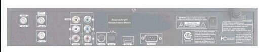
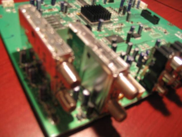
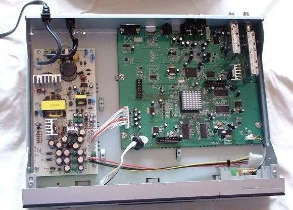
Recently I came across a used Sonicview 8000HD receiver to play with for some time, until another interesting cheapi comes alone. First thing I did was clearing up its memory from whatever was their before and loading legit factory software to it. When I then looked under the hood, I found that its internal ATSC integrated NIM tuner is made by Samsung, specs of which are given here. This tuner is also capable of decoding NTSC and Clear QAM Cable signals, but these its capabilities aren't used in Sonicview 8000HD. I found that the tuner has 2 ports: In and Loop Through Out, but in a standard receiver only ATSC In port protrudes through the receiver's back panel allowing to attach coax cable to it. Full of good intentions to fix this sudden "design deficiency", I removed all PCBs from the box, drilled a hole in its back panel for the Loop Out port, and ordered an extended non-standard F-connector on EBay to let this newly discovered port out of the box.
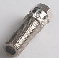
That's when the story began to unfold. :) The EBay Chinese store selling that connector confirmed shipping instantly... only to send me another email 2 weeks later saying they are out of stock on these connectors, but expect more at some unspecified happy-go-lucky hour. And instead...offered me a standard short F-connector plentiful everywhere. After some mulling of the issue and usual mumble-jumble that almost lost forever long F-connector was magically found, and I even received the shipment tracking number this time around. After waiting just a little more than a month, I finally got one in my mailbox...from Singapore. :)

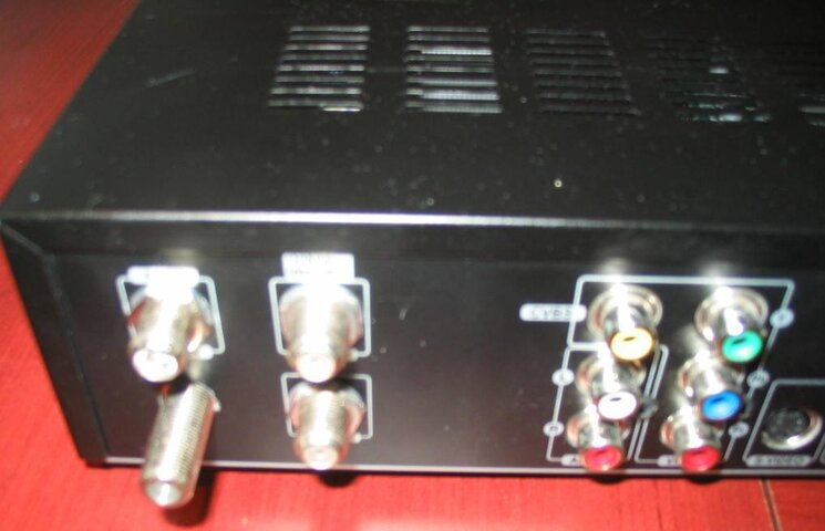
Now it was time to check my Sonicview ATSC Tuner ports performance! I connected the extended F-connector to its hidden Loop Out port, mounted all PCBs back into the receiver's case, closed the cover, hooked up coax cable to the new port, switched the STB and my second TV On, and...vu a la. A strong signal appeared on my second HDTV. The Loop Out port is not powered, it passes through signal beautifully regardless of Sonicview being hooked to a power outlet or not. I scanned OTA channels, and got the same channels showing up on both Sonicview connected TV and my other HDTV with an integrated ATSC tuner. The list of OTA channels scanned was the same, regardless whether I hooked a coax to SW ATSC Loop Out port or not, so signal loss on the Loop Out is negligible. Great! Now I don't need to buy an expensive OTA Pre-amp and a set of splitters to get OTA channels showing up on our new HDTV in the bedroom! :sob:
 

Attachments

  • SV 8000 HD factory STB.jpg
    SV 8000 HD factory STB.jpg
    9 KB · Views: 688
  • Sonicview 8000 HD Tuners.jpg
    Sonicview 8000 HD Tuners.jpg
    36 KB · Views: 928
  • F male to F female long.JPG
    F male to F female long.JPG
    5.4 KB · Views: 669
  • SV-8000-HD open.jpg
    SV-8000-HD open.jpg
    53.9 KB · Views: 1,545
  • SV 8000 HD with ATSC Loop Through Port.jpg
    SV 8000 HD with ATSC Loop Through Port.jpg
    49 KB · Views: 957
Last edited:
I started this thread, as more out of warranty SV HD receivers are getting sold for a lot less on EBay, Craiglist and such, and new owners can do easy mods to expand the STBs legit functionality and extend trouble free lifespan...
Now I don't need to buy an expensive OTA Pre-amp and a set of splitters to get OTA channels showing up on our new HDTV in the bedroom!
The mod adds a non-powered ATSC Loop Through port to the STB, allowing you to run coax cable from OTA Antenna to SV8000, and from the STB to a second HDTV or PC with an ATSC Tuner Card without a noted signal loss to independently watch local OTA (Over-the-Air) channels on both. It can also be used as an extra DVB signal Pass Through Port from another Satellite Dish to a second Sat Receiver connected to another HDTV or a PC with DVB Tuner Card, if you want to avoid parallel cable runs by combining signals from OTA Antenna and second Sat Dish into one coax outside the house, running it through the SV8000 STB's ATSC In and Out Ports, and separating signals at the second STB with a set of diplexers.
 
Last edited:
I hink this is the norm now for sv8000hd.:
[FONT=arial,helvetica,sans-serif]"The Sonicview 8000 v2 HD PVR has finally arrived, Introducing a built-in ATSC Off-Air HDTV tuner. Record your favorite shows on either a USB Flash Drive or external USB 2.0 Hard Drive in MPEG format. Recordings can easily be burnt onto DVD or other Storage Media. As Stated above, DON'T MISS OUT, ORDER NOW!!! [/FONT]
[FONT=arial,helvetica,sans-serif]Features include: Fan for dissipating heat, HDTV/ATSC Off-Air Tuner, USB PVR Ready, USB Flash Drive Upgrades, 7 Day EPG, HDMI, Component Video Output, Dolby Digital 5.1 (Optical Out), Picture In Picture, Picture In Graphic, Plus much more"[/FONT]​
 
Please do not post ads in this thread! You are welcome to share mods or repair tips and techniques of this STB useful for others. :up
 
Last edited:
Repairing SV 8000HD Power Supply

My 8000 started refusing to come back on after switching the power switch on the back (sometimes it would eventually but it took 10 minutes), and also when you saved settings or edited the channels the screen would flicker. I replaced both C10 and C24 capacitors with 1000 uf 16v caps and now the 8000 works like new.
They are located in a 5V section, so 10V caps will work fine.. What is important for longer life is the temperature rating of the cap. The Factory cap is rated at 105 degrees-not good enough. (Screw up when extra hardware is added that heats up the box). Look for a 135+ degree cap, and it will most likely last longer than the box.

This is a common problem with older versions of SV 8000HD. Pics below show, what capacitors to replace, and what models to choose. Variations of this mod were posted on several sites, and the solution may be helpful to some SatGuys' members. The repair is simple and a lot cheaper than buying a new Power Supply from SV. Depending on your performance test of the STB, one (C10) or two (C10 and C24) or even 4 caps would need to be replaced. The bad caps on this PS often won't look damaged in any way. The root cause seems to be low capacitors quality in the early STB production runs or higher required Caps voltage rating after adding an extra Board. Its power supply isn't overheating during STB operation, in fact its the coolest area around even without active cooling, which is not required for it. But some Caps, in particular C10 were reported to overheat, hence higher Caps temperature rating may help too. Putting in an Add-on Board increases power drawn from the PS, though it was designed for it, possibly with some errors. Broadcom chipsets are the hottest components in the STB, and, as other reported, need both passive and active cooling to operate normally, especially with older Add-on card models.


Here's the detail "How to fix" advice, composed from various sources:

"I have SV-8000HD. When I connect all I can see is two green LEDs on mother-board. (I Saw those lights from Top vents). No display at all on the Front panel. When I press the power button on front all I see is tiny blink or orange light.Same thing when I hit power off (Red Remote) button at the top? What's wrong... By the way, everyone's who's power supplies have died, the front display reads nothing at all. If your receiver is stuck on "BOOTING" it's likely not the power supply. Read through the FAQ's and learn how to force boot the factory file via USB.

I started with C10, got it out, and first thing it landed on was my Capacitance Meter: 700uf at best. Dropped a new one in, (which read 1053uf) and tried out the PS. "Booting" - Great! power on! etc....3.297vdc, and very clean. My first choice in quality Japanese electrolytics is Nippon Chemi-Con, which has been in business since 1931... the quality of electronics is dependent on the quality of the electrolytics.

Verified cap polarity and proper solder connections. If polarity was reversed on a cap you would find out in a much more spectacular way than that. It would explode, literally. You can tell which way the caps go in. The polarity is marked on the board with a " ) " mark outside the circle where the capacitor mounts for the side of the capacitor with the stripe (Look at the old capacitor and the marking on the board before removal and you will see what I am talking about). I would not pull and twist on the old capacitor, you could damage the board. Use solder wick (desoldering braid as it is also called) and remove the solder from around the leads. You can then pull the capacitor right out and install the new one. When you install the new one the leads will be really long. Leave them long and slide them in the holes. Then bend them to the side (one on way and the other the other way). This will hold it in place while you solder the leads. Solder them in (google how to solder for video tutorials). Then after the solder cools (do not blow on the solder, you could cause a cold solder joint) straighten the leads up and cut them as close to the solder as possible. That is it! Install the board and fire it up.

Or warm one contact at a time, slight sideways pressure (tipping on the cap, if you have the room) to pull wire through the board. Repeat process to loosen the other one. Looks like they used a lead free solder with large copper area around the leads. This makes it difficult to desolder with a lower wattage iron. A 35-40 watt flat head iron should do the trick. The original C10 is a 1000uf 10v capacitor so you have exactly what you need. You can look at your power supply and the values of the capacitors are marked on their sides btw. Just for informational purposes, it is fine to go up with voltage from the original value but not down when replacing capacitors. The only issue with going up is the higher the voltage, the bigger the capacitor gets."


Where to find 1000uF Capacitors required?

1000µF 35V 20% 85C Radial-lead Electrolytic Capacitor (low temperature rating, but reported to work fine) generic by Radio Shack
Model: 272-1032. Good to replace both C10 and C24 caps.
RadioShack 272-1032 Radial-lead Electrolytic Capacitor

1000uF 25V 16x15 20% 7.5LS 105C Radial Leaded Electrolytic Capacitor, Nichicon model UHE1E102MHD3, sold at Mouser.com. Recommended!
Nichicon UHE1E102MHD3 Aluminum Electrolytic Radial Leaded Capacitor
 

Attachments

  • Cap 1000µF 25v 105c Alum. Electrolytic MCMElectronics.jpg
    Cap 1000µF 25v 105c Alum. Electrolytic MCMElectronics.jpg
    6.1 KB · Views: 741
  • SV8000 Replace 4 Capasitors 2.jpg.JPG
    SV8000 Replace 4 Capasitors 2.jpg.JPG
    130.1 KB · Views: 944
  • SV8000 Replace 4 Capasitors.jpg
    SV8000 Replace 4 Capasitors.jpg
    435.5 KB · Views: 1,358
  • SV8000 Power Supply Replace Caps C10_C24.jpg
    SV8000 Power Supply Replace Caps C10_C24.jpg
    77.1 KB · Views: 1,347
  • Cap 1000µF 25v 105c Alum. Electrolytic Nichicon_Mouser.jpg
    Cap 1000µF 25v 105c Alum. Electrolytic Nichicon_Mouser.jpg
    3.6 KB · Views: 676
Last edited:
Status
Please reply by conversation.
***

Users Who Are Viewing This Thread (Total: 1, Members: 0, Guests: 1)

Who Read This Thread (Total Members: 3)

Latest posts