What is inside a two way splitter ??

Status
Please reply by conversation.

jenom

SatelliteGuys Family
Original poster
May 22, 2006
84
1
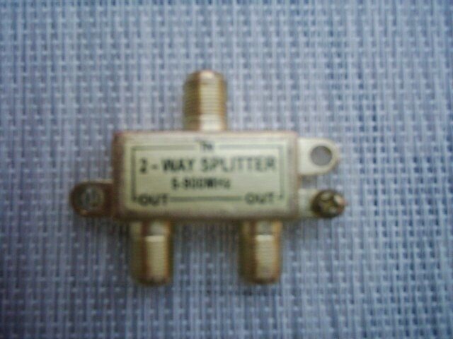
I found two type of two way splitters out there:

A) All Port Power Pass
B) One Port Power Pass (second port DC blocked)

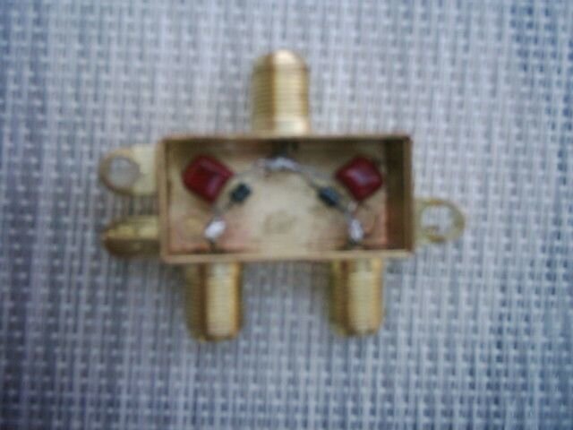
Just wondering, if anybody took any of this splitter a part by removing rear cover to see what is inside ???

My best guess is , that :

"A" has two diodes with their positive (anode) is connected to each of the output ports (the two receivers) , so when they send a positive voltage, it will go through to the LNB,: and the two cathodes (-) of the diodes are joined together at the input port (LNB)

"B" has a diode and a capacitor inside, with the diode + (anode) connected to the "power pass" port , so the reciver's positive voltage wil go thru;
and the capacitor is connected to the other port (DC block), so only the signal will go through, not voltage; the other sides of the diode (cathode -) and the capacitor is joined together at the input (LNB) port

Could anyone verify or dismiss my theory, and share any related experience??Thanks!
 
sounds good to me

I would assume both A and B are correct, until proven wrong.


enhancements:

In A, the diodes might have little high frequency bypass caps across them to pass the RF.

In B, the diode might be replaced with a wire.

If this were a TV splitter, it might just have a small capacitor for each leg (no diode - no power pass)
Or, it might have a resistor on each leg, with no capacitors around them. (because for TV, it wouldn't matter)
...or a resistor in series with a capacitor for each leg.
 
No, i am not talking about cable/tv splitter- it is splitter for satellite (2000-2300mhz)

I have taken already two $1.00 2 way cable/TV splitter 950 Mhz a part....had only a copper wire inside !

Yes, in "A", i was wondering about how the signal would go through the diode, since the diode would "rectify" it, which means cutting of the negative part of the signal.

I am thinking of a small experiment to build "A" by using the already open $1.00 cable/tv splitter;
replace the copper wire with two diodes and a parallel by-pass capacitor and connect one LNB input and 2 receiver and see what will happen ??

Just need to make a calculation (an educated guess) to choose the value for the capacitor to pass 10,750 without too much loss.
 
Last edited:
No, i am not talking about cable/tv splitter- it is splitter for satellite (2000-2300mhz)

I have taken already two $1.00 2 way cable/TV splitter 950 Mhz a part....had only a copper wire inside !

Yes, in "A", i was wondering about how the signal would go through the diode, since the diode would "rectify" it, which means cutting of the negative part of the signal.

I am thinking of a small experiment to build "A" by using the already open $1.00 cable/tv splitter;
replace the copper wire with two diodes and a parallel by-pass capacitor and connect one LNB input and 2 receiver and see what will happen ??

Just need to make a calculation (an educated guess) to choose the value for the capacitor to pass 10,750 without too much loss.

They may be using an L/C circuit for passing the specific frequency's. You may need to wind a torrid.
 
Yes, in "A", i was wondering about how the signal would go through the diode, since the diode would "rectify" it, which means cutting of the negative part of the signal.
Not a problem. The capacitor carries the signal.
The diode passes power to the LNB, not the signal.
Use a rectifier in the 1N400x family.
The lowest voltage part in that series, is 50 volts.
Make sure both banded ends (cathode) go together and to the LNB.
That way, the receiver putting out 12 volts can't be back-fed by the receiver putting out 18 volts.

I am thinking of a small experiment to build "A" by using the already open $1.00 cable/tv splitter;
replace the copper wire with two diodes and a parallel by-pass capacitor and connect one LNB input and 2 receiver and see what will happen ??
Whichever receiver selects Horizontal polarization (+18 volts) wins.
The LNB switches to H.
If you had band-stacked LNBs, it just wouldn't matter.
But, since nobody has those, it's a moot point :cool:
Just need to make a calculation (an educated guess) to choose the value for the capacitor to pass 10,750 without too much loss.
Any cap above 100pf will pass the 900-2000mhz signal just fine.
Keep the leads straight and short, so they don't become inductors and block the signal. :rolleyes:
 
How to build a $1.14 splitter

Thanks for all the info, so I went ahead and built one $1.14 "all port power pass" splitter.
You may ask why $1.14 : $1.00 + 14% taxes (Ontario/Canada)
(see attached photos)

It works as it supposed to be , both receiver can power the LNB.

Will be using on 123W and 30W, both has all the channels i care for is on the "V" polarity, so there won't be any conflict if both receiver is on, and tuned to the same sat.

It is definately an easily do-able project for anyone who has some previous electronics experience and already owns a small soldering iron, and has some loosed diodes + capacitors (they could be recycled from any old/defective printed circuit boards.

Building a "one port power pass/one port DC block" is even simpler, since one side could be connected with a straight wire (DC power pass) and the other side with a capacitor (DC block/signal pass)
 

Attachments

  • DSCI0017.JPG
    DSCI0017.JPG
    40.2 KB · Views: 1,498
  • DSCI0020.JPG
    DSCI0020.JPG
    33.9 KB · Views: 4,544
Last edited:
what's the big picture?

I don't quite understand what you are trying to achieve.
You have two receivers, two satellites, a splitter, and only one dish/LNB?
Ya gonna go outside an move the dish between two birds that far apart when you want to change satellites? :rolleyes:

Or maybe you really have two dishes (each with an LNB) and some other switches...?
Although we were dealing with the fine detail of your actual question in the thread above, if we knew your overall goal, there might have been some better answers.

I'll guess you built two of the adapters described above, hooked each to a separate dish/lnb, and also to a 2-input switch connected to each receiver.
The proper solution would have been to use two dual-output LNBs, in this case, but you're adding a 2nd receiver and trying to avoid swapping out the LNBs... ?
Is that about right ?

Let us know how this all works out. :)
 
Splitters

I have two 33" dishes and a 24" starchoice dish, pointed to 123W, 97W and 30w, .......but they ALL have only a single output linear LNB and I want to connect them to two receiver (thru a 4x1 diseqc switch)

Of course, I could replace all three single output LNBs with a dual output LNBs, but buying three dual output linear LNB would be a somewhat expensive , plus I would have 3 extra single output LNB for ????

Here comes the $1.14 splitter into the picture: By making three of these splitters for a total of $5.00 and my problem gets solved.

There is only one small limitation, when both receiver is ON, both must be on the same polarity, otherwise it will create a conflict between "V" & "H"

However, this is no problem, since the majority of the channels we will be watching are all on "V" polarity (verified on Lyngsat)

I think we discussed here "splitters" in the most deepest details, more than the avarage sat users needs/wants to know about them.

Thanks again for everybodys very useful input !
 
Last edited:
The satellite splitters have a ferrite bead with wires wrapping around the bead. You have the spitter only about half completed. The diode is used to send the dc only in one direction and prevent it from going down the 2nd output. You can use a 1N4148 signal diode. It will pass enough current to operate a LNBF. The capacitor is used to pass the high frequency signal. Take a look at some of the Dollar Ttores for the $2.00 (CAN) satellite splitters.
You need the ferrite bead and the coils of wire to maintain the impedance. Remember you will also cut your signal in half, 3 db loss (plus connection losses) when you split the signal. You should end up with about a 3.5db loss.

That's one of the reasons I was talking about winding a torrid / balun (ferrite bead) this will keep the impedance at 75 ohms. If he changes the impedance he will have a higher SWR and alot more attenuation.
 
Status
Please reply by conversation.

Users Who Are Viewing This Thread (Total: 0, Members: 0, Guests: 0)

Who Read This Thread (Total Members: 1)