wiring for trx1520 both to the sat and the actuator arm

Status
Please reply by conversation.

akimbobo

Active SatelliteGuys Member
Original poster
Aug 7, 2006
19
0
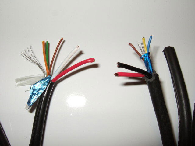
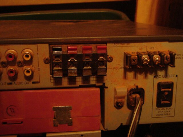
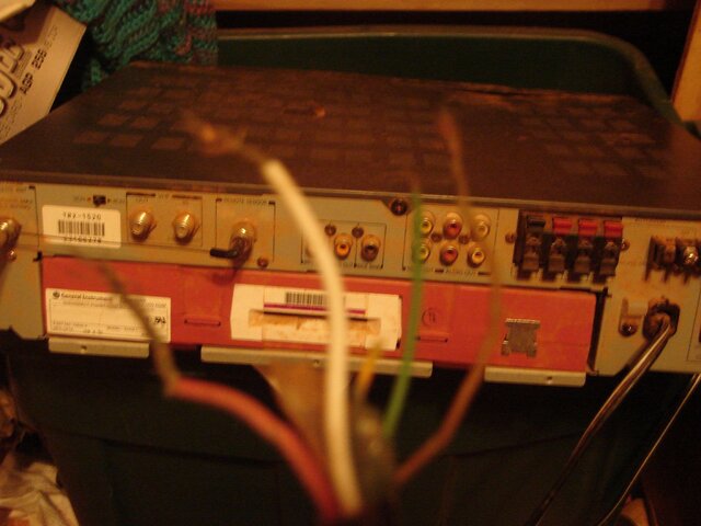
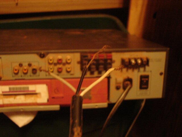
This is for the wires going to the back of the reciever

I have found one post that kinda helps but my wires are not the basic red white and black colours :(

I do have red and white but I also have brown and green

I need to know where they go

for the actuator arm I have three wires one white and one black one red.

Thanks for any help at all :)
 
Last edited:
usually there are two different ribbon cables ( that i know of)
one has a bigger black & red wire there are m1 & m2 (motor wires)
and usually wrapped together with a blue yellow brown & bare wire these are for the motor sensors
another cable with only three wires usually red black and white are for the polorotor / corotor

the other version ribbon cable has a bigger white & red wire ( m1 & m2 again)
and four smaller wires wrapped with them are orange green brown & bare (no cover/casing)

each actuator is a bit different ( if your motor is wired and has a diagram then a picture would be great) usually ground (orange) or (yellow) & pulse (green) or (blue) some use a third wire usually brown (+5V) only connect this wire if you know it needs a third wire.

the big wires are the main motor movers wires connected one way they move the dish east - west reversed they move the dish west- east
 

Attachments

  • DSCF3348 (2).JPG
    DSCF3348 (2).JPG
    50.5 KB · Views: 188
I guess I can't edit the subject of my post. I wanted help hooking up the wires to the back of my sat receiver. I hope there was no confusion


here are pics of the back of the receiver and the wires that need to get attached to it.


the second pic wires go red white green brown

the third goes red black white

thanks for the reply :) i hope that picctures explain what i need
 

Attachments

  • Picture 147.jpg
    Picture 147.jpg
    792.9 KB · Views: 219
  • Picture 149.jpg
    Picture 149.jpg
    799.5 KB · Views: 211
  • Picture 150.jpg
    Picture 150.jpg
    689 KB · Views: 221
motor wires (second picture)
big white & big red = M1 & M2
small orange = ground (these are hooked up on the top row)
small green = pulse (these are hooked up on the top row)


polorotor wires ( three small wires together) third picture ( these are hooked up on the bottom row)
red = +5V
black = Ground
white = hat symbol or pulse output (depends on what unit on how its marked)

hope this helps
 
thank you very much I am now up and running and trying to arc the dish :)

I just have to get a ku/c band feed horn so I can get the free feeds on my mpeg 2 receiver :)
 
Status
Please reply by conversation.

Users Who Are Viewing This Thread (Total: 0, Members: 0, Guests: 0)

Who Read This Thread (Total Members: 1)