GOES 16 GRB downlink vs GVAR

That's something that has to do with the receiver. That's why I posted the image of nothing to show what my receiver (SDR) was seeing before it hooked it up to GOES 16.

At 121W longitude, I am probably outside of the range of GOES-16, especially with an 8.5' dish and a circular patch antenna tuned for a lower frequency.

I would like for you to try to see if you can see GOES West as it would be at 135W. You can use it to tune your system. Mabie try for (16) again.
GOES West spectrum would look just like my analyzer picture of GOES East (13). Post 9
All signals are linear polarized, you should have no problems seeing EMWIN at 1692.7 Mhz even with a circular polarized patch, I use an 8' dish and have a huge EMWIN signal on GOES East, I would try with the Outernet antenna. If you can't see GOES West then something else is wrong.
My suggestion. I do recommend to build a wavegide feed (coffee can feed) though as they seem to work best.
 
  • Like
Reactions: N6BY
...
I would like for you to try to see if you can see GOES West as it would be at 135W. You can use it to tune your system. Mabie try for (16) again...
Yes, I have given up with GOES-16 for now. And when it moves to 75W it will be even farther out of reach. I am only 14 degrees of longitude from 135W vs 32 degrees (46 next month) for GOES-16 EAST.
...GOES West spectrum would look just like my analyzer picture of GOES East (13). Post 9
All signals are linear polarized, you should have no problems seeing EMWIN at 1692.7 Mhz even with a circular polarized patch, I use an 8' dish and have a huge EMWIN signal on GOES East, I would try with the Outernet antenna. If you can't see GOES West then something else is wrong.
My suggestion. I do recommend to build a wavegide feed (coffee can feed) though as they seem to work best.
I plan on shopping for some 5 inch diameter cans today. I also ordered a new LNA and cable.

Are you making any progress decoding and generating images from GRB?
 
N6BY,
Did you happen to come across any 5" cans?
I am curious of what amp you were using to try to find GOES 16?
What connector does the amp use?
Please don't think I'm being pushy, I have my reason for asking.
Trust me I understand the frustration when things don't work. Been there done that.

Are you making any progress decoding and generating images from GRB?

Nope, still waiting on my cheap China box. The computer for this is later as it's something to see...
 
N6BY,
Did you happen to come across any 5" cans?...
I tried two grocery stores (with tape measure in hand, LOL) and the best I could do was a can of Crisco and a Quaker Oats container. The Quaker Oats container is all cardboard and the Crisco can only has a metal bottom and the rest cardboard. So I'm going to use the metal round end of the Crisco and tape it to the Quaker Oats. Then I'll wrap some thin metal sheeting around the Quaker Oats container.
I am curious of what amp you were using to try to find GOES 16?
What connector does the amp use?..
I bought it on eBay and it was shipped direct from China. It has SMA connectors, but I don't know what chip it uses. I have attached a photo.
lna.jpg


Nope, still waiting on my cheap China box. The computer for this is later as it's something to see...
Doesn't your NOVRA S300 work for this?
 
Do you have a "N" to SMA short length cable?
I may have another option for you then the
Crisco and a Quaker Oats containers...

Amp Kinda looks like a mini circuits broadband amp.
That very well may work don't give up on it yet.
Though it really needs to be in an enclosure for RFI protection. Thanks for the pic.

Doesn't your NOVRA S300 work for this?

Yes the Novra works fine for GRB but it has to be removed from NOAAPORT service. That's why I have an S300 on hand.
 
Where did you get the dimensions for the can wave guide pictured in post #4? I tried a few online calculators and for 1690MHz they come up with a much shorter can (but same diameter). Also they have the probe much closer to the back of the can than yours.
 
Waveguide length has been taken from other designs, and my choice, The longer waveguide doesn't allow additional modes to propagate inside. The probe length was determined by trial and error. Seemed to work best there. The general is about 1/4 wavelength from the back.
Dia. of waveguide is .75 of an wavelength.
 
N6BY, You want it (see below)
Sister Horn.JPG

That's why I was asking you about the N to SMA cable.
It's the sister to the one I have been currently using. If you want it.. just say so.
 
Thanks for the offer. But I already have SMA to F adapters. My cantenna is built. I just need to mount it on the dish when its daylight.
 
Sounds good. Offer still stands.
Those broadband amps can have 1 major issue and that is.. They can overload on strong signals due to their bandwidth. This can cause far less then ideal performance.
This is for anybody out there, An amp that is exposed like that can pick up signals from surrounding RF sources and amplify them. The term is RF coupling. Shield and ground your active components.
 
I mounted a "Quaker Cantenna" on my Birdview dish today. I used a longer probe than the one shown in post #4 (1 3/4" vs. 1 5/32"). I also shielded the LNA with aluminum foil as suggested. The Quaker Oats container is wrapped with tin sheeting, held in place and sealed with clear tape. The cantenna is mounted on thick PVC.

QuakerCantenna.jpg


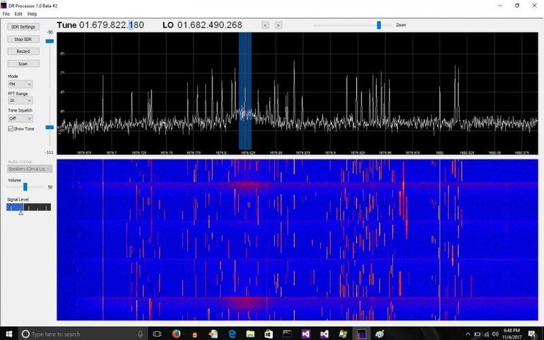
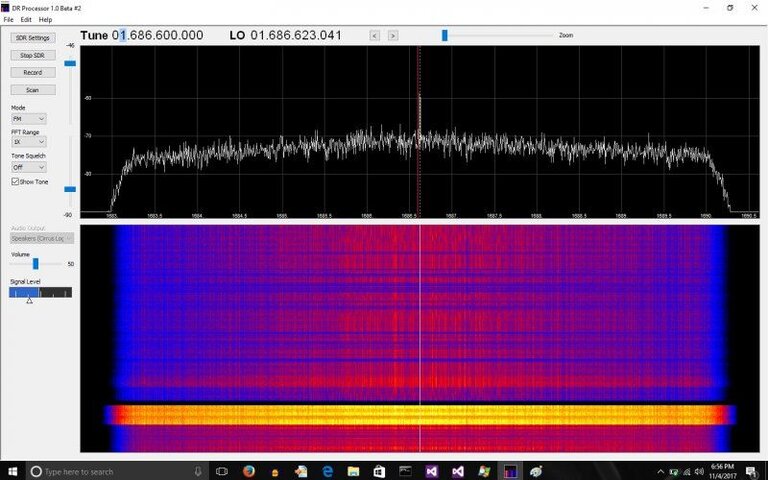
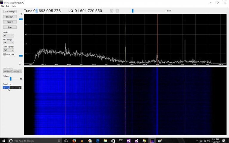
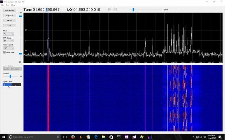
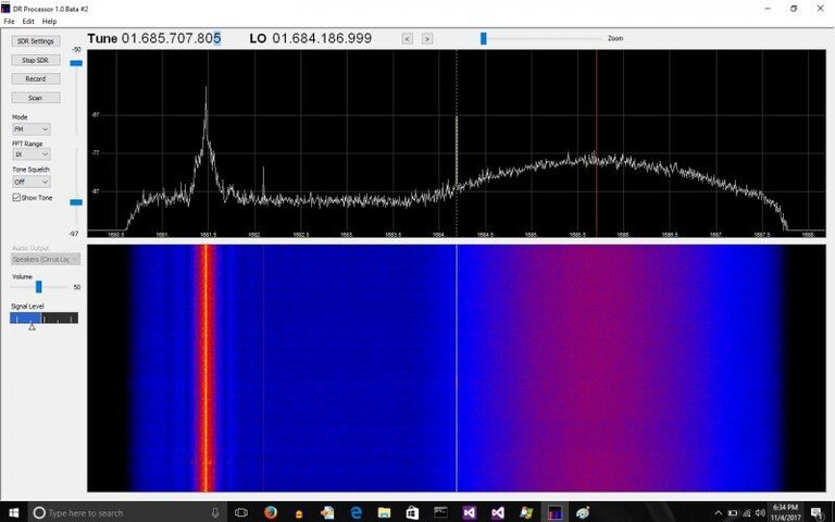
It works much better than I expected. I tried it on both Goes East and West using an SDR Play and my 'DR Processor' program to view the spectrum. Even with a linear (vertical) polarity feed, I saw GRB on both Goes East and West. It was at a slightly lower frequency, but stronger on GOES west. I also saw HRIT and dozens of intermittent signals in the 1679 to 1680MHz range. I have attached DR Processor screen captures below.
GoesEast1.jpg GoesEastGRB.jpg GoesEastHRIT.jpg GoesWest .jpg GoesWestGRB.jpg

In the last screen capture on the right, the wide band signal centered at 1685.6 has an SNR of about 10 dB. It looks like it could be GRB but have no way to verify it.

My next experiment will be to add a horizontal probe with a 1/4 wave longer feed line and combine them to see if I can get better reception of the circular polarized signal.
 
N6BY,
All Right, Good job!
That what I wanted to see.
Want to clarify a few things though.
I saw GRB on both Goes East and West.

On GOES East (75W) and WEST (135W) the wide band signal is GVAR not GRB, GRB is only on GOES 16 (89.5W).

All signals below are linear polarized.
GVAR is at a center Frequency of 1685.7 Mhz at 4 Mhz wide, EMWIN 1692.7 Mhz, LRIT 1691 Mhz.

GRB is dual circular polarized.
Only GOES 16 (R) has GRB at 1686.6 Mhz at 12 Mhz Wide, HRIT 1694.1 Mhz.
Images that I can make out are...

GoesEastGRB.jpg.. This is GVAR, When you can decode this signal you'll see 3 knobs pop out of the top of it . One in the center and the other 2 on each end. GVAR is BPSK modulated at 2.11 Mbs. It's not DVB-S2.
GoesWest.jpg... Centered on EMWIN.
GoesWestGRB.jpg... GVAR on the right (wide signal) and I'm not recalling what's of the Left of GVAR. TLM or DCS?

Your screenshots I couldn't make out the spectrum frequencies very well just the large center frequency.
With this new cantenna you should be able to see GOES 16 as well. I bet Quaker oats never expected to be used in this fashion.
Ahh... the pride of getting the signals you're looking for.
 
Back to the dimensions of the feed.
After N6BY asked me about the probe position info I did some research and found an error in my drawing in post #4.
The dimension should be a distance of 3 5/16" NOT 3 7/16" from the back.
This again doesn't match the calculator above but it's what I made years ago and worked, as seen in the results.
I would suggest the the calculator dimensions be used in future designs, but the feed length can still be varied.
Scaling down some other feeds info suggests that it should be .92 of a quarter wavelength = 1.52"
Calculation found by 1.66" X .92 = 1.52"
I apologize for the error and I don't like to post inaccurate info as it don't help anybody. I will have the drawing on post 4 removed or I will get the corrected one in it's place.
When I did the tests to determine the probes position it seemed not to very a ton but there were sweet spots and that's what I chose.
Probe length was done the same way.
 
Last edited:
N6BY,
All Right, Good job!
That what I wanted to see....
Thanks, it was refreshing to see some real signals and not artifacts.

...With this new cantenna you should be able to see GOES 16 as well....
The first three screen captures are from GOES-16 (75W), and the 2 on the right are GOES-15 (135W). So I can see both. :)

Any idea what the dozens of signals from 1679 to 1680 are? They are all low bandwidth, and some are intermittent.

I am currently trying to compile 'xritdemod' from the Open Satellite project. Am running into issues with dependent libraries, and the dependent libraries have dependencies, etc.

Any suggestions for ready to use software to view the data?