Home-made OTA TV window antenna

polgyver

Creative Tinkerer
Original poster
Pub Member / Supporter
Sep 21, 2010
487
368
Toronto
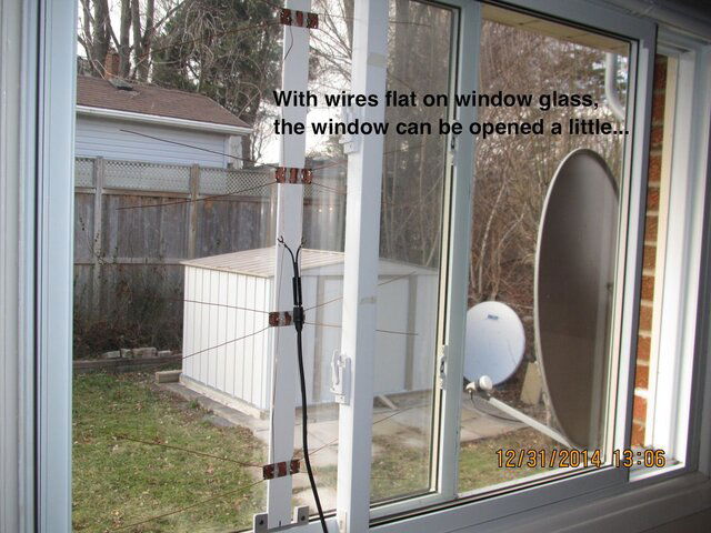
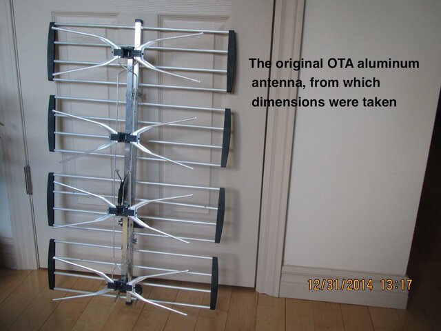
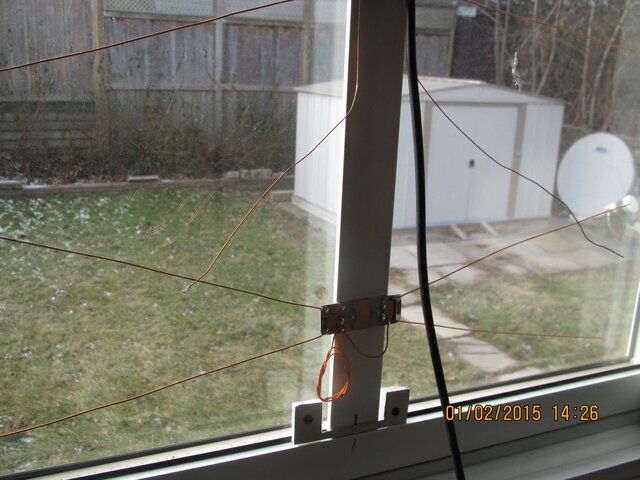
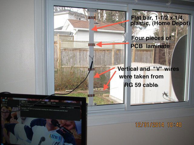
As there are many descriptions of antennas made of coat hangers, one similar version has been tried, based on
dimensions taken from factory- made antenna.
I made 3 models of such antenna : one is utilized in our friends' apartment window (7-th floor, facing West - towards downtown Toronto). Such antenna pulled in 31 channels TV, most of Buffalo.
My 2 models of this antenna also scanned in 20-something channels, but we can reliably receive only about
6-8 channels.
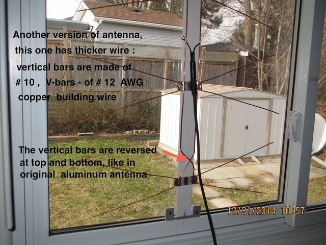
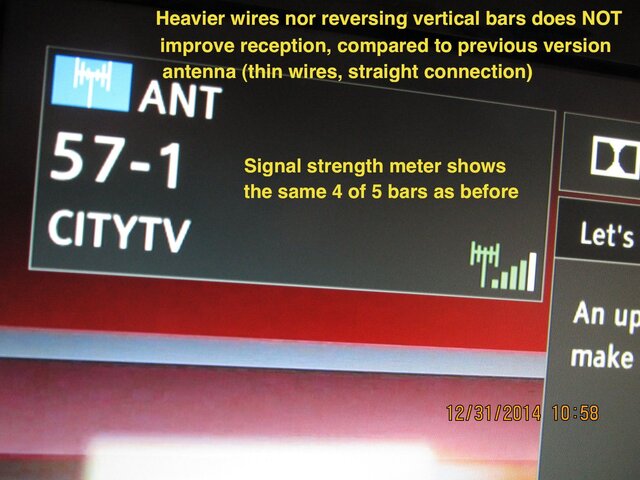
What is puzzling me, reversing vertical bars of antenna does not make any difference in reception.
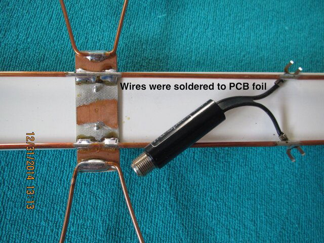
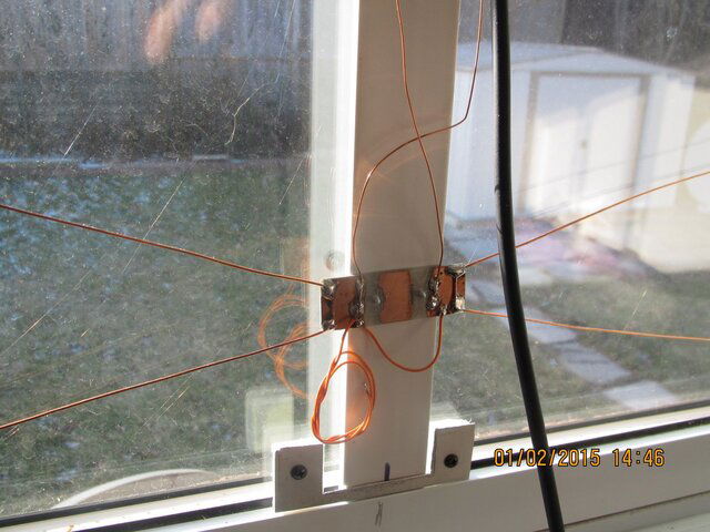
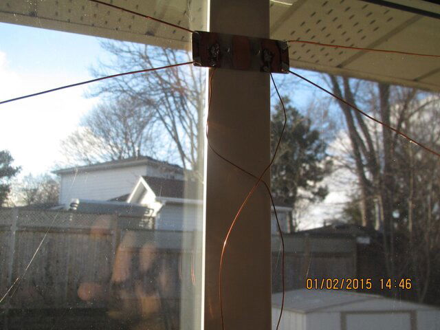
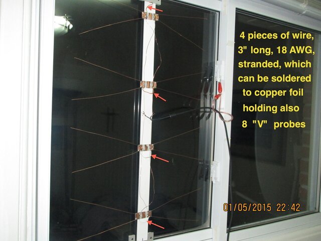
Annotated pictures follow :
IMG_0432.JPG IMG_0433.JPG IMG_0434.JPG IMG_0438.JPG IMG_0440.JPG IMG_0446.JPG IMG_0447.JPG IMG_0449.jpg IMG_0450.JPG IMG_0451.JPG
 
  • Like
Reactions: polgyver
polgyver,

Are you aware of the OTA section of the Digital Home Canada forum? There's a vast amount of information on there about building TV antennas, and more experts on design and antenna computer modelling than you could ever wish for! For the most acclaimed 4-bay antenna design there, search for 'mclapp 4-bay'.

As to your design, be aware that the antenna from which you took the dimensions is optimized for channels 14 to 69 (it's designed for the far-eastern market), whereas an antenna designed for the (current!) North American market will be optimized for channels 14 to 51 (which means the elements will be bigger). Using the latter's dimensions will give you more gain on North American channels.

The phasing harness (your vertical elements) MUST be crossed, otherwise the signals from the end pairs of bow ties will be out-of-phase with the inner pair and will lead to phase cancellation (resulting in very low signal levels).

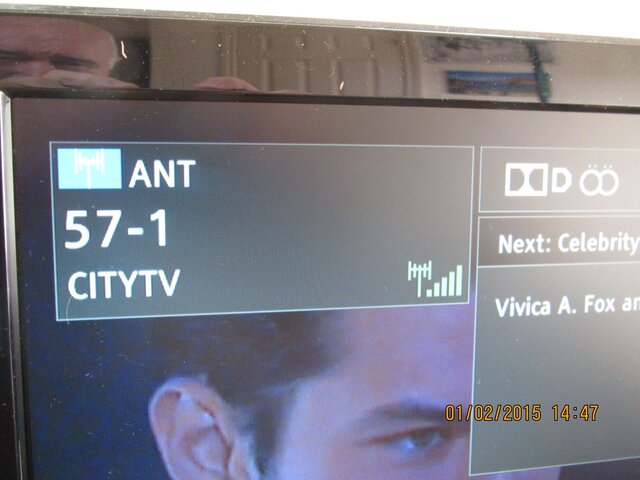
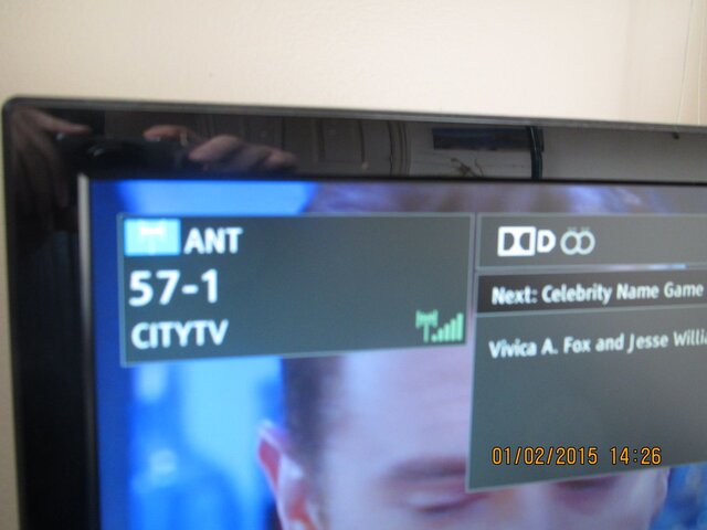
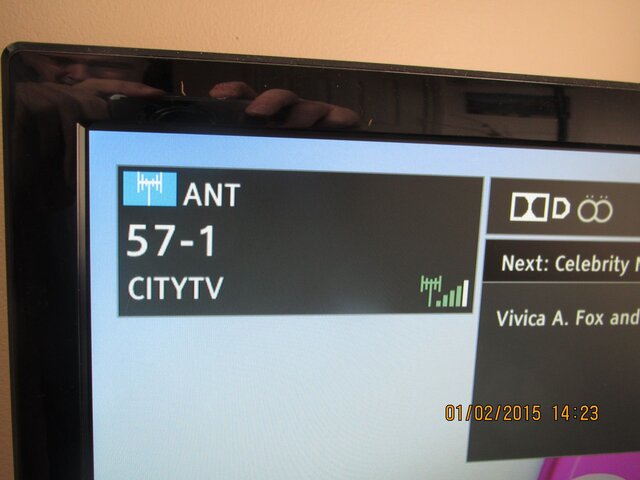
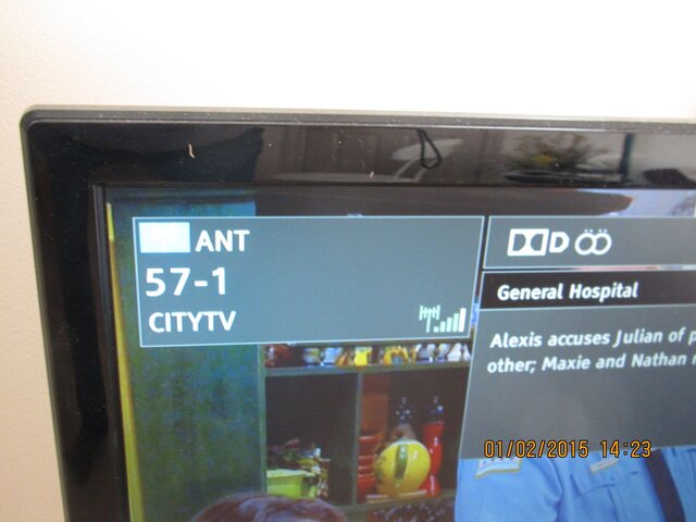
The signal level meter on your set is almost certainly logarithmic, so it takes a huge signal increase to get from four to five bars, but much less to get from one bar to two. As a result, the meter won't show small changes in signal levels once it gets to four bars (unless it's on the four/five threshold).

I like your implementation - the use of the plastic strip and copper laminate is most innovative!
 
  • Like
Reactions: polgyver
Nice job. I'm curious about the picture with the soldered foil. Looks like the dipoles are shorted together. How does that work?
Nice job BUT find a way separate the two main wires all the way down. Maybe cut the metal in the middle of each of the four bow ties.
Please write back with your findings.
Thanks
 
Nice job BUT find a way separate the two main wires all the way down. Maybe cut the metal in the middle of each of the four bow ties.
Please write back with your findings.
Thanks
To answer you and jorgek:
The main wires were and are separated. Sorry, if my 9-th photo somehow misled you. I had 2-sided PCB, but took care to remove some copper foil on BOTH sides, using small grinder, was too lazy to remove all, that,s how the reminder is visible on the photo.
But your questions gave me some hint : What, IF I left the copper foil on one of these plates?
So, I tried to imitate this situation, and the results are puzzling :
Soldering a piece of wire on the bottom of antenna (basically, bridging it, or, shorting) did not cause any signal strength drop.
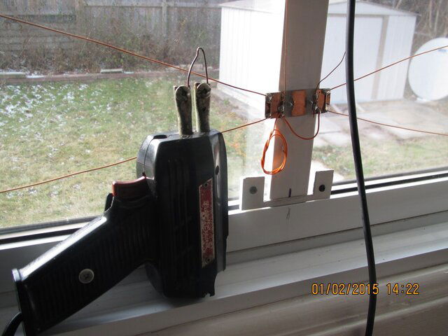
Nice to have soldering gun handy and do some changes "on the fly" without even switching off TV.
I expected that, after shorting out the "rails", the TV reception would be lost, so, prepared longer piece of wire for making inductive coil (wrapping the wire on a pencil) and bridging the rails with such coil.
It was not needed, as the short bridge did not hinder reception.
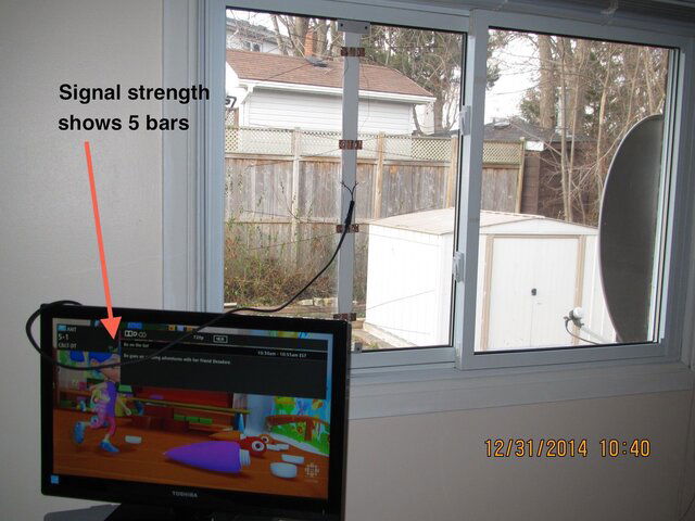
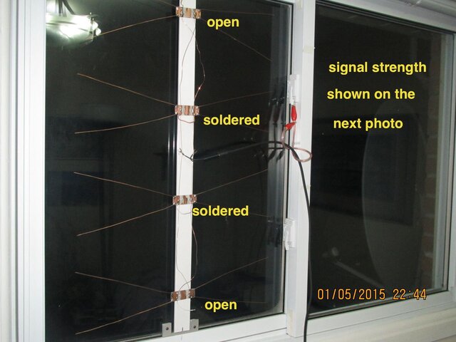
The best signal strength (5 of 5) was after disconnecting the rails from the 2 bottom "V" probes (so only 3 pairs of probes worked).
Finally, I re-soldered the rails as they should be - with top and bottom probes reversed. Signal was still 5 of 5, with bridging wire joining the rails.
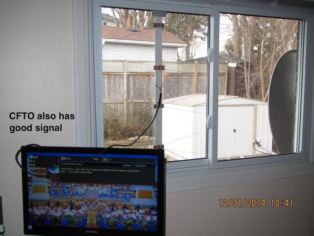
Other TV programs (with stronger transmitters) were 5 of 5 all the time.
I agree with DVB-S2 statement that my TV's signal indicator is imprecise, using only 5 steps.
A few pictures follow
IMG_0468.JPG IMG_0476.JPG IMG_0475.JPG IMG_0474.JPG IMG_0473.JPG IMG_0471.JPG IMG_0470.JPG IMG_0469.JPG
 
That was an interesting experiment. As often is the case you can make changes which will not affect strong signals. However the real test is with weak and marginal signals. Its difficult to test with off air because UHF especially weak ones tend to vary in intensity by the minute. I find with OTA the best time to test antennas is on a cold clear sunny day.
 
That was an interesting experiment. As often is the case you can make changes which will not affect strong signals. However the real test is with weak and marginal signals. Its difficult to test with off air because UHF especially weak ones tend to vary in intensity by the minute. I find with OTA the best time to test antennas is on a cold clear sunny day.
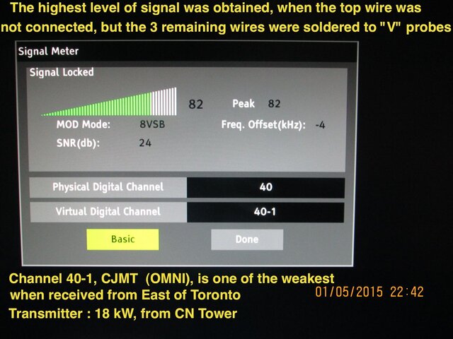
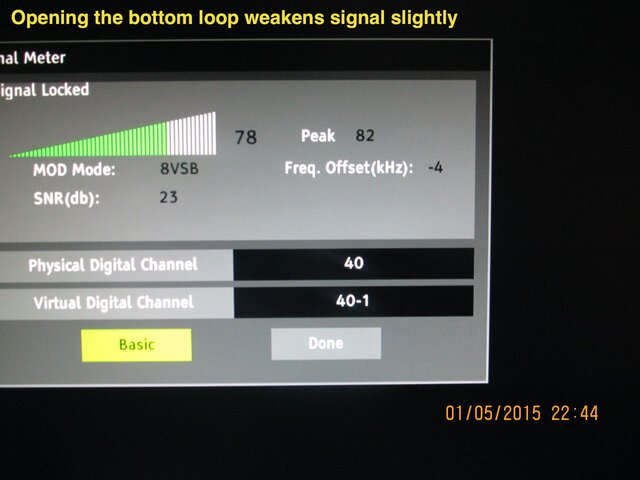
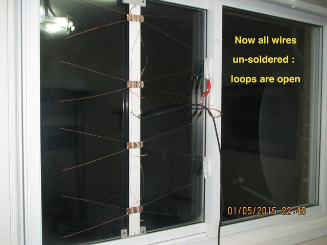
Got some unexpected results...
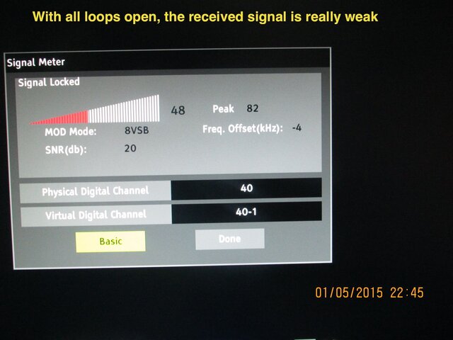
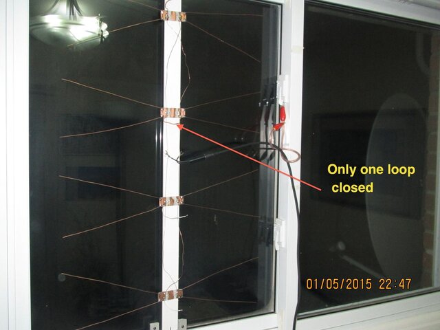
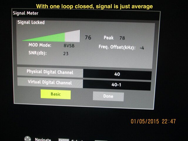
Partial "shorting" the "V" probes with small loops of wire improves reception. Shorting the top probes definitely spoils reception. So far, I got no idea why. In these frequencies, there is really no "short", as semi-circle of wire has certain inductance.
Finally, I figured out that my 24" Toshiba TV has decent signal meter, not only the 5 small bars shown when changing channels...
Annotated pictures show more
IMG_0498.JPG IMG_0499.JPG IMG_0500.JPG IMG_0501.JPG IMG_0502.JPG IMG_0503.JPG IMG_0504.JPG IMG_0505.JPG
 
  • Like
Reactions: jorgek
From your location rabbit ears will work as well. Years ago TV sets came with a loop antenna that would attach to the 300 ohm connector for UHF. For local reception they worked quite well.
 

Users Who Are Viewing This Thread (Total: 0, Members: 0, Guests: 0)

Who Read This Thread (Total Members: 1)