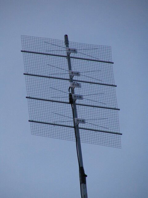
The mesh reflector is 40" wide by 36" tall.
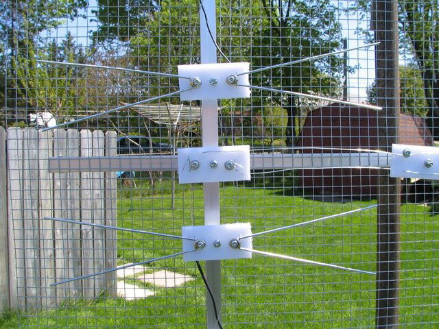
Each V of the bowtie is made up of a 14" long wire bent at 7". The points of the V are 3" apart when bent. (this should make approx. 24deg bend).
Two of the V bent wires are mounted to a piece of plastic cutting board. A finishing washer, bolt and nut is used to hold the V wire of the bowtie in place. You will need to file two slots in the washer for the wires to pass through. The plastic cutting board pieces are each 1.25" x 3". One hole in the centre to hold to the antenna, and another 2 holes, each 3/4" apart from the centre hole. In the outside two holes mount the V wires to make up the bowtie. Place the V wire, then finishing washer held together with the bolt and nut. Further out from the outside holes a small hole is drilled in the cutting board above the top and below the bottom wire. This hole needs to be tight against the V wire. The wire connecting all the bowties together will go through this hole latter and wrap around the bolt under the finishing wire and back out the other small hole. The reason for this is to help hold the V's of the bowtie in place, and not just rely on the bolt and nut for proper placement.
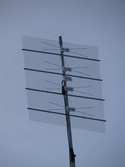
From the top of the wire screening to the bottom the bowties are spaced as follows:
Top of screening (reflector)
3.5"
Bowtie
7" (2 x 3.5")
Bowtie
3.5"
Signal pickup point (just use a cutting board piece with no bowties)
3.5"
Bowtie
7"
Bowtie
3.5"
Bottom of screening
For the left to right spacing I used 10" as my spacing number. The bowtie centres were spaced 10" from the sides of the screening which places the bow tie centres 20" apart.
The bowties were mounted 3" above the screening.
In my different designs, I have used anywhere from 3" (2 x 3 = 6") to 4" (2 x 4 = 8") spacing between the bowties with no noticable difference in signal strength.
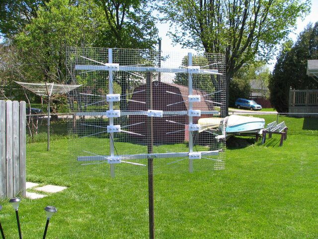
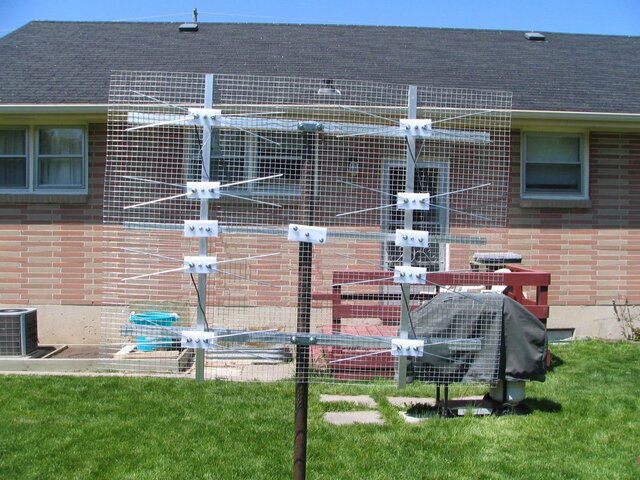
Starting out with a 4 bay bowtie, be sure to reverse the connections of the top and bottom bowties when wiring them up and be sure the wires do not touch each other. When you look at the different manufacturers web sites this will be apparent. The theory in this is that the time for the signal to travel down the wire 7" will put the signal 180deg out of phase, so reversing the connections will put it back in phase to add to the next bowtie. The cutting board piece with no V wires connects the top and bottom 2 antennas together. (think of the top two bowties and the bottom two bowties as being separate antennas and you want to hook them up in phase) Since it takes the same amount of time for the signal to travel down the wire the 3.5" from the top two bowties as it does to travel up the wire from the bottom two bowties, they are connected together left to left and right to right. i.e. no twist. Now this so far has the 4 bowties hooked up. Now to connect up the two bays of 4 bow ties, once again connect the left to left and right to right together. This time place another piece of the cutting board with no V's half way from each connection and this will be where you take your signal feed from. Once again the signals will be in phase and add together. This same theory could be used to add two 8 bays together to create a 16 bay antenna if needed. Hopefully studying the pictures will make this all clear.
With 3 sections of TV tower and a 10" mast I am able to pickup RTN11 which is 70mi from me. My location for reception is poor as I have trees and hills. I do use a Channel Master pre-amp, but do need a higher tower. Due to the hills, I am unable to reliably receive the stations 50mi from me. The antenna is about 35' high now. Where I live, 60'-70' towers are not uncommon.
If you add up my measurements, they don't come out to 36" high but only 28" high. I think I just spaced an extra 4" at both the top and bottom of the reflector. This will help the signal to the top and bottom bowties. If you want to increase the rigidity of the reflector, you can bent the top and bottom inch or two at 90 deg to increase its strength.
The small box in the very centre is where you attach your 300 ohm twinlead or a balum.

") it's more the challenge and satisfaction of building it yourself.......
it's more the challenge and satisfaction of building it yourself.......")
