
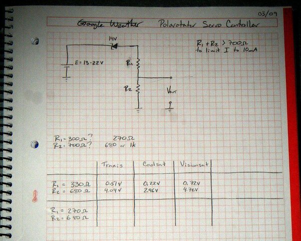
I've got the servo out of a spare cband dish on my workbench. So far I've got a simple zener diode and voltage divider circuit setup in a breadboard that gives me 3.5V to 5.6V for Horizontal and 0.07V to 0.3V for Vertical. The ranges are a result of different receivers.
Ok, so that's looking good, and it'll be easy to hook up to a uC for servo control. I've got an AVR ready to burn. I don't expect too much trouble with any of that.
...But, I am curious, does anyone have any opinions on how best to package this and hook it up? I can do the digital electronics and servo control, but I really don't have much RF packaging experience. I want to make sure that I don't adversley affect the signal more than necessary. I'm thinking a metal enclosure with two fconnectors. The controller is hooked up inline between the CBand lnb and the receiver. Does anyone have any thoughts? Ways to make my life easier, or make the final result work better? Any thoughts on using a low-pass filter?
I will release the code and schematic when I'm done, if I'm done, if it works, etc.
Thanks.
")
")


