Polarotor Servo Controller Design

Status
Please reply by conversation.
his thread: " SG2100 Insertion loss", Satcom1 was suggesting 1 microhenry..

Aha, great thread. Thanks for the link. I built a similar "splitter" using a 2.2uH inductor, and when I use it to test my breadboarded controller with a real signal, I get no quality loss. I'm surprised how well it works. Hopefully I'll get it off the workbench and into the dish this weekend.

Here's a pic of the splitter, and a pic of a Visionsat getting a signal through the splitter, and controlling the servo depending on what channel I'm watching.
 

Attachments

  • dscf1807.jpg
    dscf1807.jpg
    127.5 KB · Views: 283
  • dscf1809.jpg
    dscf1809.jpg
    92.3 KB · Views: 293
Way to go equant! Good to see breadboarding spirit is still alive. Sounds like you have most of the kinks in your design worked out. I am anxious to see the details.

I can see a few add'l advantages to using a PIC with A/D in your design. One is the derived voltage variations between rx's could be compensated for in FW, or even use a 2nd A/D input to make your compensation adjustment pot be under uC control. That might also allow for the odd skew to be manually tweaked when watching those birds that need it.
Another advantage would be increased memory and function for expandability on a proven design.
Staying with a digital only input, and increasing the component count by one using a logic gate/buffer chip of your choice to conditition the digital input should allow you to 'tap' the feedline at a very high impedance with unnoticed loss or current load. This should also allow for an acceptable degree of isolation between the potential 20+ VDC and the uC's low level DI.
........but as Anole said, it's all pretty much a moot point if you already have a functional unit...........lol
I agree the DiSEqC based design is a 'waste' of a function that could be better used in it's intended multicommand structure, but some dont utilize DiSEqC at all so is as viable as any other including 22khz detection. Hacking a DisEqC or 22khz switch to sense it's state should not be difficult, and would already have the RF/DC fitering components, the chassis, and be setup for constructing a well shielded F connector passthru assy. The obvious advantage is no tweaking for variations across rx brands, as these outputs are standardized and fixed.
Congrats on your solution, good forward thinking. Cadsulfide is one of you all PIC guys too. Now I know there's a few more of yall [you TOO Anole!], this ol' hardware, hardwired hardhead knows where to come for some serious uC spoonfeeding. If ya' cant teach an old dog new tricks, sometimes you just have to shoot him and get a new dog.............lol
 
I described this project to a buddy at lunch today.
He had recently discovered the 
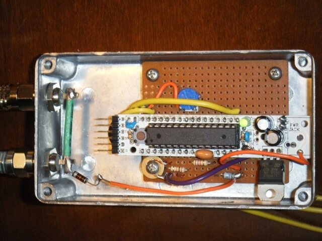
Arduino board, so he suggested it.
Would certainly be suitable for rapid-developing something like this project.

I wanted two LEDs (green & blue?) to indicate 12/18 volts.
Then, two buttons to tune the servo forward or reverse (and maybe an enable toggle switch).
Figured the LEDs could blink off as you press the buttons, to indicate a change of pulse width.

Also, the project needs to be able to remember the settings after a power-down.
So, I wanted an e² chip or feature - the Arduino has that built in.

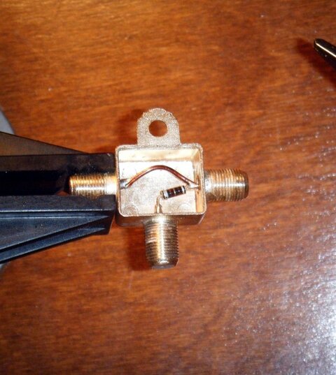
It's got an analog input, so you could set it to 2v and 4v (whatever) to detect the 12/18 volts on the coax, buffered through the circuit shown above.

Plenty of I/O pins are available.
The board is inexpensive, especially as a one-of-a-kind toy.

I thought about adding a one-line LCD display, but frankly couldn't think of a good use. :rolleyes:

20 years ago, I'd have programmed an Intel 8051 chip, in assembly language.
This thing has a high level language development system.

Just something to consider.


Ya better test it before ya bet any money on it.
I think those are wound for the wrong end of the spectrum.
...and the core material is, too.
 
It's still not in the bud, but it's passed the "24 hours in operation on the workbench without going loco" test. I have the code on another computer, so I'll post it later, but here's the schematic and a pic of the final assembly.

I used the RBBB Freeduino board from modern devices for rapid prototyping. Ultimately I'd probably use a 8pin pic. I was unwavered in my decision to use a zener diode and avoid using A/D. I still think this is the right decision. Less power, less code, more robust. I see no reason to use A/D for a binary sensor.

The real test will obviously be once it's in the BUD; seeing if it ever drifts or wanders off course or overheats in 110 degrees.
 

Attachments

  • polarotar_servo_controller.jpg
    polarotar_servo_controller.jpg
    98 KB · Views: 321
  • polarotar_servo_controller_schematic.gif
    polarotar_servo_controller_schematic.gif
    159.1 KB · Views: 341
Can't you keep it in the house?

Oh yeah, I could do that. Duh. Should have been doing that to test. In the long run I'll move it outside I think...

I have my receiver hooked up to two Ku dishes and a BUD. If I keep the controller inside, that puts it between the receiver and a Ku motor, a Diseqc switch and multiswitches. That would probably work, but that means the servo would be moving more than it needs to be, since it'd be switching polarity even when I'm not using the BUD. Seems like excessive wear. Plus I have another project in the works that will require it to be out there.

For some people's situation, it might make more sense to build it and keep it inside so you don't have to worry about weatherproofing it. Building it would be much easier, and most people would already have their servo wires coming into the house anyway.

Where do you keep your Gbox? Inside or out? For now, I have to use my 4DTV to move my dish, but at least I'll be able to ditch my reference sheet that tells me what polarity channel 1 is on each bird, and I can leave the 4DTV receiver on Digicipher channels I actually watch. How luxurious.
 
Where do you keep your Gbox? Inside or out?
Inside, never though of outside.

I have my receiver hooked up to two Ku dishes and a BUD. If I keep the controller inside, that puts it between the receiver and a Ku motor,.....
True. I'd do a little re-wiring to keep it in the house, but that's just because of the weather here.
 
Any new developments on this project? Pics or code? Keep up the great work! :up
 
I've been running it for a several days (a week?) now, and it's pretty sweet.

I'm going to get a final schematic and the code up in the next few days. I've tested it with two servos, and I think because of their age, they respond differently. What is a difference in 90 degrees for one is not for the other.

What I did was have the AVR report the servo positions for H and V via serial. I then hardcoded them in the firmware and re-uploaded it, so the pot is now unused. I also had tried to make the controller smarter by looking to see if the polarity has changed before setting the servo value. This causes some flakey changes, especially when you first start the receiver (you have to flip between polarities sometimes when you turn on the receiver. Then it works fine.) An easy fix, just want to change it before posting the code.

So the servo issue... I think to make it easiest for people, it needs two pots, one for H and one for V. If someone's going to have it inside, this is pretty good, you could have a nice little box with two pretty knobs. Seems good. For those of us that will have it outside, hardcoding the positions might be best to avoid temperature shifts, but two trimmer pots could be used.

I'll get something final soon.
 
good work

Yea, nice implementation. - :up
And so clean, I'd even consider trying an old servo-based feedhorn some time!
edit: might still suggest those green & blue LEDs, to indicate which polarity is being sensed.

Also a fine test bed for what Sadoun should shove into the next Gbox version!
Only in that case, his can know which bird you are looking at, and recall the independently tuned settings for -that- satellite! :cool:
 
A simple improvement for your RF side is to incorporate 2 inductors in series; one to block RF frequencies (950- 2150MHz) and one for low frequencies (22kHz - if you have switches in your system).

In selecting your inductors you must juggle several parameters:

Current capacity - since this circuit is a very small load it shouldn't be a big issue although I'd like to know what current a polarotor servo takes when operating.

Value (of course..) - defines how much it "chokes" the RF or 22kHz.

SRF (self resonant frequency) - A very important parameter. Defines the frequency at which your inductor is no longer an inductor to RF. At this point it might look like a piece of wire and even a capacitor. The larger the inductor (size and value) the lower this frequency will be. You don't want to operate close to this.

Although you may not see any drop in quality on your signal, it is possible you are attenuating the signal at your tap. Layout is key. Grounding is key. VERY short connections are key.

This a perfect application for a microcontroller. Great idea. I'll likely have to do something like this when I replace my pansat 3500 (has servo control) with a DVB-S2 blind scan unit soon which is unlikely to have polarotor control. I'll likely adapt or just copy what you have done.
 
I realize that this is a very old thread at this point, but in case anyone is interested in a project like this, I just completed building one based on the original work by equant a while ago. If you have a BUD with a Corotor feedhorn and you want to run an FTA receiver without being tied to an analog receiver for polarity control, this is one solution. Information about my project box is available at http://budfoot.com <click the "files" link>

And thanks to equant for sharing his work on this in the first place.
 
Incredible

I tried to post to this thread this morning, and it would not post saying the Thread was older than 316 days... And here you are... Cosmic intervention!!!
Anole had posted the link to this from another thread yesterday.
This is very good solution to my problem and many others as well.
Thanks to Equant, Anole, and all the others for the input and photos and links .
Trying to do this myself, however I am an absolute idiot in comparison to you guys, but I'm learning slowly...
Thanks for posting your link, and looking forward to doing this myself, with help from a tech friend of mine that can push me along here.
I'm thinking you guys should think commercial distribution of this deal or combine it with a GBOX with Sadoun's blessing or something like that... Imagine the # of folks looking for this solution, not just here in the Americas but Europe, Middle East and all over the place.
Great idea, and I would be curious as to everyone who is trying this, commenting on whether or not they went with interior or exterior installations etc. as per the last conversations on this a year ago.. thanks for the new link, HB
 
budfoot, nice design and work.

You can start a new thread about adding polarotor controls to the GBox. Do a survey. If there is enough responds and interest, we might pursue it.
 
You can start a new thread about adding polarotor controls to the GBox.
... If there is enough responds and interest, we might pursue it.
I thought we already had this discussion . . . last year . . . and it was a go.
Here's hoping the renewed interest will lite a fire. - :up - :D
Please see all my comments above for enhancement ideas.
 
Status
Please reply by conversation.