
Positioner wiring
- Thread starter pjcl
- Start date
- Latest activity Latest activity:
- Replies 51
- Views 13K
You are using an out of date browser. It may not display this or other websites correctly.
You should upgrade or use an alternative browser.
You should upgrade or use an alternative browser.
SatelliteGuys Fund Raiser
100%
- Total amount
- $585.00
- Goal
- $350.00
Donation ends:
- Status
- Please reply by conversation.
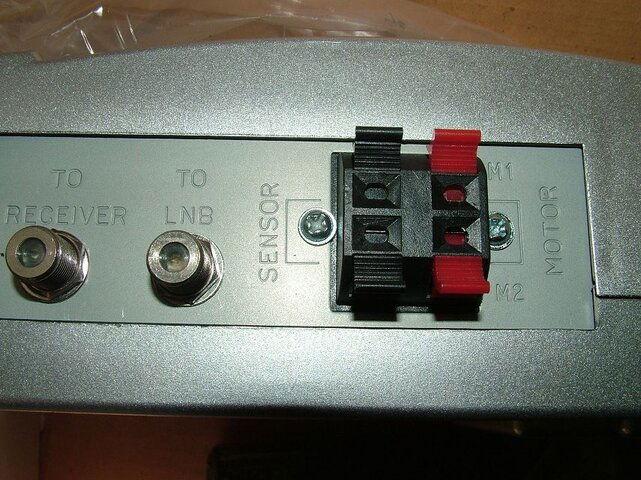
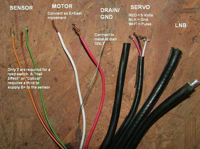
Great, I begin to see the light at the end of the tunnel - thanks, FaT Air. So, since I'm using a DMX741, I will not connect the servo wires, right (I don't have one)? The motor wires, if my understanding is correct, are interchangeable - one extends the arm, the other, retracts - is this correct? This means I have to connect in such a way that pushing the left button on the positioner equals arm extension, i.e., eastward movement, correct? About the sensor wiring, which one goes on top and which one goes to the bottom? Will it depend on how the wiring in the actuator is done? And why are these needed? - Could I just move the dish to one side or to the other manually? I apologize for my ignorance on the subject, I'm new to C-band, as ku band stopped being a challenge. Thanks.
The servo wires are normally used with a servo(poloarotor). Use then for what-ever as you use an LNBF. The sensor wires don't matter when using a reed switch(2 wire) sensor. Matters if using a Hall or optical(3 wire. requires externaly supplied voltage to third wire) Motor wires, as needed to make programming easier, East command = East movement of dish. Could be extend or retract depending on what side of dish the actuator is on. Sensor counts are needed to program the G/Vbox satellite positions. Set the actuators extended limit switch so no damage is done to actuator or dish.
So, in my case, I just need to connect *any* two of those three wires to the positioner? And about the DRAIN/GND wire, it only needs to touch metal on the side of the dish? Can it be the LNB, or does it have to be a different part? Thanks again, FaT Air.
PLEASE LOG IN TO GET RID OF THESE ADS!
The two that go to the reed switch. Might have to open the actuator to see which two that is.( and to confirm it is a reed switch)I just need to connect *any* two of those
I just attach to metal inside the actuator, Mounting screw for the barrier strip for the motor and sensor wires works for me.Drain wire


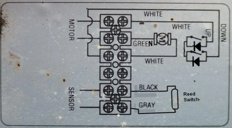
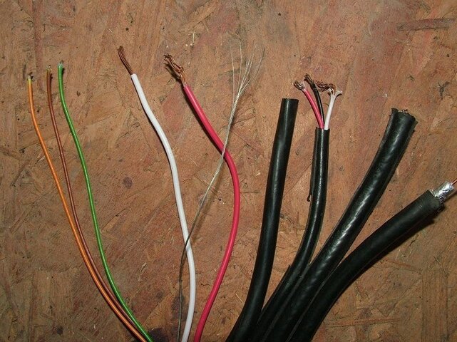
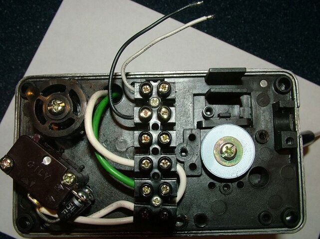
Green and white are your motor power wires. The other two are for the sensor. Sensor wires don't have polarity so the order does not matter.
Your m1 and m2 wires if reversed will cause your dish to move the wrong direction. If you push the east button an it goes west reverse m1 and m2. The "drain" wire is probably nothing more than ground and is not necessary.
Your m1 and m2 wires if reversed will cause your dish to move the wrong direction. If you push the east button an it goes west reverse m1 and m2. The "drain" wire is probably nothing more than ground and is not necessary.
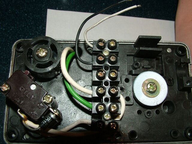
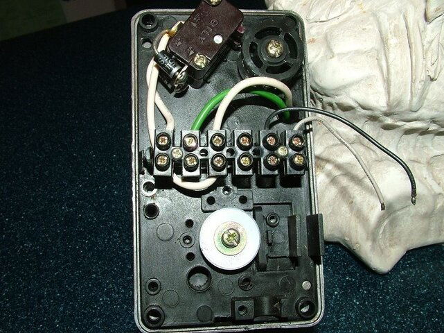
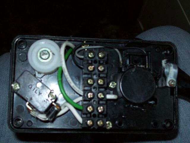
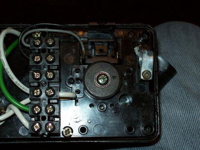
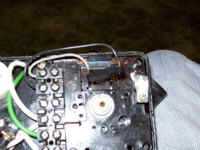
See previous post - You'ii need to take it apart a bit more, should find the magnet wheel inside, reed switch should be very close to it. (I've seen some actuators that use a micro switch and cam instead of a reed switch and magnet wheel) Re-assemble careful to get the cams in the proper location.Can't tell where they are supposed to go... any ideas?
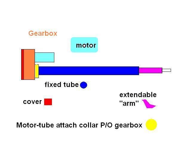
For ease of working on it, you could remove the motor from the tube and take it apart on the workbench.
PLEASE LOG IN TO GET RID OF THESE ADS!

Behind there somewhere, just take it apart carefully. there is a geartrain and the sensor switch, important to put it back together as it was, if you have to take some of the gears out to repair the switch. Usually the gears can stay in place. All of them are different in the gear box so you'll have to answer your own question, when you take it apart.
Attachments
Still the wiring inside the actuator arm
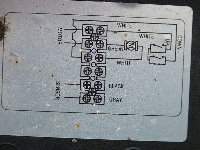
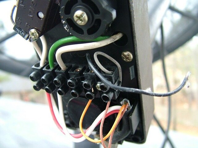
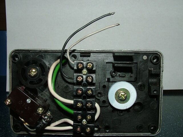
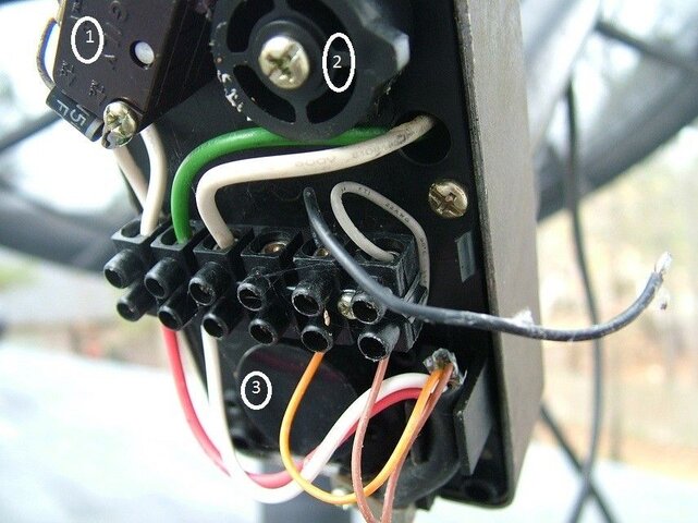
Guys, I still can't figure out where these two wires go. This is a SuperJack II + HQ actuator. I took it down to have a better look. Motor wires (red and white) were in place. Two of the thinner wires (brown and orange, in the case) were, too. Then I had these two thinner wires, one black, one white, which I found loose and I can't absolutely find where they go. Taking the unit further apart, to where the dented wheels are visible, didn't help. Any suggestions?
Guys, I still can't figure out where these two wires go. This is a SuperJack II + HQ actuator. I took it down to have a better look. Motor wires (red and white) were in place. Two of the thinner wires (brown and orange, in the case) were, too. Then I had these two thinner wires, one black, one white, which I found loose and I can't absolutely find where they go. Taking the unit further apart, to where the dented wheels are visible, didn't help. Any suggestions?
Attachments
- Status
- Please reply by conversation.
Similar threads
- Replies
- 3
- Views
- 979
- Replies
- 13
- Views
- 2K
- Replies
- 20
- Views
- 5K
- Replies
- 4
- Views
- 2K
- Replies
- 3
- Views
- 1K