RG6 Quad installation

  • WELCOME TO THE NEW SERVER!

    If you are seeing this you are on our new server WELCOME HOME!

    While the new server is online Scott is still working on the backend including the cachine. But the site is usable while the work is being completes!

    Thank you for your patience and again WELCOME HOME!

    CLICK THE X IN THE TOP RIGHT CORNER OF THE BOX TO DISMISS THIS MESSAGE

jaylaudeman

New Member
Original poster
Apr 17, 2006
1
0
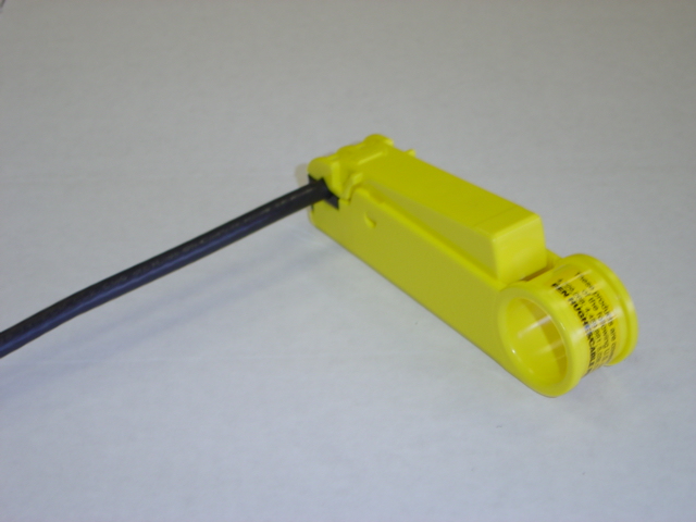
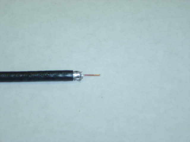
I work for a factory that makes wire harnesses for RV's. I'm in charge of all coax end installation. I usually install about 1000 Thomas & Betts SNSRG6QS connectors a week and sometimes 600 per day. Right now we are using all Belden RG6 which I know they should be using the RG6 connectors on and not the QS but but they don't care. But my issue is that the customer is looking to switch to Belden RG6 Quad Sheild cable. We got a spool in the other day and I have been testing out ways to install the connectors quickly since I would have to do so many ends. The instructions that come in the box of connectors says you should peel back the first braiding then slit the first foil and then peel back the rest of the braiding then install the connector. As you know that takes a while to do all of that for one connector, so I got online and tried looking around and it said to set my stripper to cut threw the first set of braiding and foil and peel back the inner braid and put the connector on. Which way should I be doing it, because I know if i strip threw it, it would make it go a lot faster but is the electrical contact between the sheilding going to be up to standard? I purchased a coax flaring tool to try on it but just using that isn't going to work because you still have that outter foil on there and the connector will not go flush. Normally I can install a single connector on RG6 cable from start to finish in about 10 seconds, with the quad sheild I was only getting about 20-30 seconds per connector, and when you times that by the amount of connectors installed it adds up.
 
http://www.dishstore.net/product_info.php?cPath=53&products_id=61

http://www.dishstore.net/product_info.php?cPath=53&products_id=60

http://www.dishstore.net/product_info.php?cPath=53&products_id=94

If you use that Stripper, that cable compression tool, PPC Cable connectors and regular RG6 Cable your life will be much much much easier.

The Quad Shield cable is not necessary in an RV Installation since your not dealing with a very long run or have to deal with interference. Besides that, Id hate like hell to have to install 600 ends on quad shield cable because your hands will be soar as hell and you will probably need some sort of coax insertion tool like a bodickey...
http://www.bo-dickey.com/

There is a company called Vextra that makes a very good RG6 simmilar to Beldin. Both are great cables, but for your situation you want to get the cable which is the easiest to put connectors on.

With the above stripper you should not have to peal back the foil brading. It should look like this when your finished....

DSC00497.JPG


DSC00505.JPG
 
I agree with Claude on the CablePrep stripper. It is the best in the business.

Here is the preferred technique;

Stripping and installing connectors on RG6QS Coax


Careful preparation of the cable end is very very important, especially with quad shielded cable. Sloppy preparation will result is the ruining of the tool and failure to set the Snap-N-Seal connector properly.

1. Place the inner sleeve of the Snap-N-Seal connector with the wide end away from the end of the cable.

2. Strip off the outer jacket of the cable and a portion of the center conductor as instructed by the document provided with the tool.

3. Carefully fold back the outer shielding wires against the outer jacket of the cable evenly, exposing the inner shielding wires.

4. Carefully cut away the outer foil shielding layer, and remove it to exposed the inner shielding wires.

5. Carefully and evenly fold back the inner shielding wires evenly against the outer jacket.

6. Snap off the main body of the connector and insert it fully on the cable end. The connector is fully inserted when the center connector is level with the end of the connector, when looking inside the nut.

7. Compress the connector on the cable with the proper compression tool.


Reasons why the shield wires must remain intact and must be folded over the outer jacket

A straight cut of the outer jacket and the shield wire layer(s) down to the center conductor insulator will not allow full contact and retention of the outer shield. The shielded wires must be folded back over the jacket. Not doung so means that the connector is just slid over the shield wires and outer jacket and retention of the shield wires are held by friction, not by tightly held tension. Tightly clamping the ends of the shield wires prevents degrading the electrical contact of the shield wires, which serves as one leg of the voltage switching circuit for the multiswitch or lnb of 15-18 volts. If you are passing only a RF signal, it is not a problem, and might not be a problem for short coax runs. But on long runs, any minor bit or corrosion or separation of the barrel from the shield wires might lead to failure and a resultant voltage drop over time. This will manifest itself in the lost of the even transponders in the signal.

The industry standard is the 1/4"x1/4" strip on the coax. If the center insulator is below the center hole in the barrel, the coax has not been fully seated. Idealy, it should sit about 1/16" or 2mm out of the hole. If you a using a compression tool that applies pressure to the inside of the connector, the plunger will force the center conductor almost flush. Over time it might return to the 2mm protrusion. This protrusion is ideal in that it eliminates the "air" gap between the center conductor insulator and the female socket port. The "air" gap increases the chances of water vapor entry and corrosion. If you look at an F81 female port carefully, you will notice that it is recessed about 1/32" or 1mm.

So, folding back the shield wires enhances the electrical contact surface between the shield and the barrel of the connector. It also increases the connectors resistance to pull off. The bent over shield wires clamped by any type of connector prevents "pull off" and ensures the integrety of the connection for passage of both the RF signal, and more importantly, with dbs, the free conveyance of the lnb switching current.
 

Users Who Are Viewing This Thread (Total: 0, Members: 0, Guests: 0)

Who Read This Thread (Total Members: 1)