IMPD Grid antenna
Since I have been reading this forum and learning about theses antennas I wanted my own attempt to make one. The price is right and it's easy enough to make.
I also noticed how other users were having problems with the size of the 1M antenna and how touchy it is. So I wanted to try to make something that could be used in portable setups and in the case of doubleohwhatever used also in Home owners Assns.
And this is what I came up with.
Starters, I have never attempted using a dish less that 8' (2.39M) to receive anything from the GOES spacecraft so this was a new venture for me. I know that using small dishes at the L band are not very efficient. This is due to reflector size and feed match/ shadowing issues.
Though the offset dish has advantages over this due to the feed being removed from the signal path. In the case of the 1.2M dish it worked very well.
I also had discussions about reflector size on here as well and stick with my opinion that the 1M antenna size is very close to signal threshold for EMWIN. As far as I have known that the smallest antenna recommended was 4' (1.2M). Also I understand that size of dish may not be available or allowed for most.
The gird antenna is a simple dipole fed reflector designed for 2.4 Ghz not as one website said 1.7 Ghz. In other words this is a WIFI antenna. The antenna is primary intended to send and receive WIFI in local areas house to house or across town, It was never intended to receive a faint signal from a satellite on geostationary orbit. But that don't mean that it can't.
The antenna: TP LINK grid parabolic antenna part # tl-ant2424b
Found for 50 bucks NEW each at Officemax/Office depot this is a surperb choice.
Let get some understanding of antenna gain. Antenna gain is a function of (in this case) reflector size in relation to frequency and antenna efficiency. An antenna that has a gain of 24dBi at 2.4Ghz will not the same gain at 1.6 Ghz, it will be less.
Also an antenna that is resonant at 2.4 may not be efficient at 1.6 Ghz.
The difference in physical size is about 1/2", this is very important when your working with these high frequencies. Trip in an earlier discussion made the dipole elements longer which made the antenna much more resonant at the frequencies of interest but he left an important part out of his improvement. He left out that as he made the driven element longer so does the reflector distance increase. Though he did increase the reflector's length.
These antennas use a reflector in front of the dipole (driven element) to capture signal from the reflector. The proper reflector distance is a function of wavelength at the frequency of interest.
To find this in free air 234 divide by frequency times 12 = inches.
Exp. 234 divide 1690 = .138, times 12 = 1.66
What does this tell us... the 1/4 wavelength of 1690 MHz is 1.66"
Lets try another:
234 divide 2450 = .095, times 12 = 1.14"
What does this tell us... the 1/4 wavelength of 2450 MHz is 1.14"
See the difference. Just because the antenna receives at a frequency doesn't mean it does it well. A quick understanding of the dipole, It's impedance is 50 ohms and it doesn't need any power. It is a 1/2 wavelength long (1/4 wavelength on each leg) and it receives off of it's edges but the tips are a null point in it's reception. This element is basic and has uni gain (none) ,it's used as antenna by itself on HF a lot and in yagis for the driven element. It's attractive due to no impedance transformation needs to happen as it's already 50 ohms.

For this antenna and models alike it's good choice for the driven element combined with the sub reflector it illuminates the reflector pretty well with minimum overspill and keeps shadowing to a minimum.
But it does have it's drawbacks in this case, it can receive of off it's edges and the subreflector has slots in it, this is a place that strong unwanted signals can cause problems.
Yes, the slots are opposite of the polarization of the driven element and due to this unwanted signals would be roughly 3 dB down. However it don't take a very strong unwanted signal to cover up the weak signal your're listening for. So an improvement would be needed to the sub reflector to make is solid. The only signals you want the dipole to hear are the ones coming from the grid reflector. This was partially proven when I told doubleohwhatever to cover up the grid reflector with tin foil and he got rid of some of the unwanted garbage.

The big improvement that made this antenna "improved" was to make the grid reflector just a bit larger, not much but enough. This would be done with a very basic idea, add to it. The finished reflector now measures 48" across

Construction......
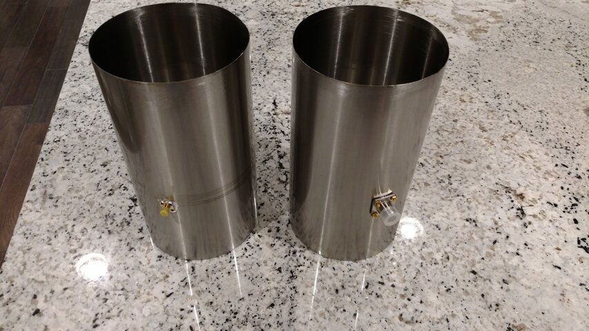
Starts when the UPS guy arrived with two big boxes.
The project requires for ease 2 antennas though you could make the changes needed to the grid reflector using other methods you must keep it parabolic for it to work well.
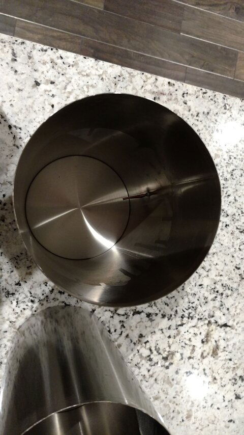
Once I determined that the reflectors would lay on each other it was time to look at the feed for the antenna. TP link has done a great job weather proofing their feeds. The plastic is thick and tough and as you can see I cut the top off to get to the driven element (above). The best way to get through the plastic is by saw, I used a razor saw.

All one needs access to is the ends of the dipole. These are in the lower bottom of the cover so you should only need to cut half way up and about a 1/4" from the edge to be able to solder extensions to the dipole to make it work for the L band. A 50 watt soldering iron worked for me,
don't use a ton of heat as you don't want to melt the coax and the support plastic.

Reweather proofing is up to you just don't use anything metal or that could degrade the reception of the antenna.
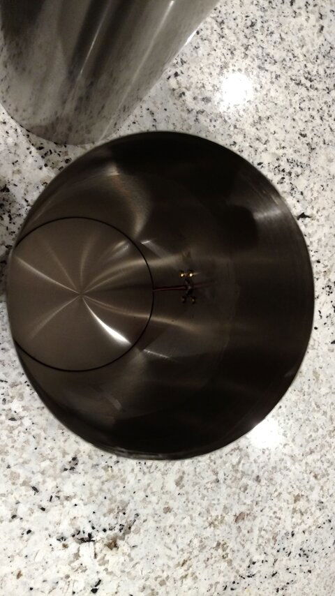
I used a stainless bolt to reattach the dipole reflector to the feed cover (after I rewelded it together). The distance is 1 1/2" wavelengths from the dipole, 2 1/2" Interesting huh. From the case it's 1 1/4". Tapped the plastic for the bolt and use a nut to hold in place

Extending the feed was done by using tap bolts to the length needed. Threaded rods shown. Dimensions shown in picture below.


One thing I don't like about this antenna is the mounting bracket is far less then stable for my desires. I would rebuild this with something more stable as you don't want the antenna moving as this can affect the error rate.
Some final suggestions, I would replace the dipole reflector with a solid sheet of material the same size and angles as the original. Another thing to improve the noise and strong unwanted signals is to use window screen on the back of the grid reflector to keep it out.
But remember that the more screen you add the more windload that antenna has, so I would keep the screen coverage around 50 to at the most 75% of the reflector keeping most of the screen towards the center.
The IMPD antenna works well for it's size and is easy to make.


")