Splitters, diplexers, power inserters, tap couplers, attenuators, in-line amps

  • WELCOME TO THE NEW SERVER!

    If you are seeing this you are on our new server WELCOME HOME!

    While the new server is online Scott is still working on the backend including the cachine. But the site is usable while the work is being completes!

    Thank you for your patience and again WELCOME HOME!

    CLICK THE X IN THE TOP RIGHT CORNER OF THE BOX TO DISMISS THIS MESSAGE
Status
Please reply by conversation.
Would DC Blocks be helpful in any way to add on any of the lines in the schematics attached?

No, in fact if they were added anywhere, something would stop working.

Another peace is will the motor still draw power from the connected via a splitter receivers, as the Power Inserter appears to act merely as a Voltage Stabilizer having presumably no pass through DC Block? If the motor still draws power from the receiver(s), in what proportion from each?

The DPP44 power inserter is a power inserter. It does not stabilize the voltage coming from the receiver(s). A microscopic amount of power may be drawn from the receiver(s) by the power inserter to detect whether the receiver is turned on or not, but even that would be speculative.

Did you modify your motor such a way that physically cuts power supply from the receiver on its command port?

The point of the mod was precisely to separate these two functions. As a result there is a physical air gap between the command port and the power port. If the motor was to melt down and short, the receiver would be blissfully unaware.

A weak point to recommend others such mod would be not only the warranty loss, but also that various motor makes have different PCBs, so an average FTA fan would rather damage the motor trying to copy someone else's solution, no matter how good the solution is. :)

The mod was specified to be only for a DG-380. At least one other member has published a similar mod for a different motor. I am not running a kindergarten. If people are bold enough to tackle a mod like this, they need to make a responsible assessment as to whether they are qualified to do it. If they are not and go ahead anyway, it is not a weak point of the mod, merely their judgement.

Anyway, if you're familiar with Six Sigma quality assurance approach, you know what I mean by all these scenarios. ;)

Many people who talk of Six Sigma are unfamiliar with what it really means to achieve this level of reliability. If this is an driving principle in your design, I suggest you reconsider some of your approaches. I respect your choice not to mod your motor. However do not delude yourself into thinking that you will achieve higher reliability through this rationalization. The motor mod is intended to increase reliability by decreasing complexity, eliminating a number of failure modes and restricting damage if certain remaining failure modes happen to occur. The approach you are outlining is weaker in these goals and introduces additional opportunities for failure.

Separately I am not sure where this was left, but it appears you believe the DPP44 power inserter is the best method to supply power to the motor while at the same time passing DiSEqC commands. I have a concern that the DPP44 could in fact provide a higher voltage than is desirable to the motor. Correct me if I'm wrong, but you then interjected that a 18V laptop power supply could be used instead of the DPP44 power inserter's power supply (that's a mouthful). Without a complete tear down and analysis of the DPP44 PI design, I need to warn you that there may be aspects of the implementation that could make this approach a kinetic undertaking. Is all of this trouble and uncertainty better than modding a motor?
 
Thanks for the detail overview and inspiration. We need to stop somewhere detailing this design due to lack of info on DPP44 PI inner working. I just wanted to use what is already available (i.e. its Power Adapter), but due to its 2 voltages the risk seems higher, so I will use the adapter from my old Apple laptop to test the idea. I have a few motor samples handy, the PI and other parts are in the mail, so as soon as it all arrives will test the whole thing. Yes, for me it worth the trouble, if it allows to avoid modding a motor, despite I can do it either.

However, in this thread it was presented to illustrate how basic in-line components work together, and what set of considerations would help to arrive at fault proof solution. It doesn't make your mod version less interesting, certainly not the last one. Just a bit different as they all are. ;)
 
on. We need to stop somewhere detailing this design due to lack of info on DPP44 PI inner working. I just wanted to use what is already available (i.e. its Power Adapter), but due to its 2 voltages the risk seems higher, so I will use the adapter from my old Apple laptop to test the idea.

I'm sorry if I missed something, but how are DiSEqC commands going to pass through a non-DPP44 power inserter to the motor?
 
That's DPP44 PI, which is in the mail. Apparently, many people don't use them, as for some installations DPP44 switch works fine without this PI. So it costs about $5 as a brand new set with some search effort, but shipping eats more from the lunch. Tried to find one nearby, but sadly around my place they're of limited supply. I "think", it will work on 18V PA with no problem. But if an attenuator of sort can be added down the line to drop voltage from 20.5 to 18V (can it without affecting motor commands signal level?), I'd rather try its own PA first, since they're family. I suspect there is no DiSEqC communication btw DPP44 switch and the PA, but when the power drawn riches a certain point, the PA switches to 28V on its own. Each so called LNB of DN (or DTV) making is in fact the whole collection of various devices under one roof, and they all draw power from the same source - this PI. But again, if it's going to suddently switch to 28V under heavy wind load resisting the motor turning, its better to drop this PA in favor of old Apple's. ;) Just recalled, I have a couple of PAs left from dead cable drop amps, need to check them out.
 
Last edited:
Perhaps I'm not being clear.

I looked at the DPP44 power inserter used for our DN subscription. The actual inserter part has two F-connectors and a cable that runs back to the power supply. How many leads are in that cable could be an important question, because it might indicate how the unit operates. If the original power supply is used, you would want to ensure nothing would cause the unit to switch up to a high voltage. If you chop off the original supply and substitute another, you would want to ensure the power inserter's functionality is not compromised.

This is likely not all that hard to figure out because the power inserter portion has a back plate held on by screws. What's inside may answer all remaining questions and issues, or it could open a Pandora's box. If I had any real interest I would have done this already, so I will instead leave it as an exercise for the reader. I'm only advising caution because the DPP44 is not intended for this purpose.
 
In-line Voltage Switching Power Inserters & Stabilizers

I see what you mean: DPP44 switch may tell this PI bugger under heavy load to switch between 2 wire sets coming from its PA. We cut 28V wire set - and we're done. It may not be the case however: some companies call their PA an "Auto switching transformer", meaning it has some brain of its own, which we can also cut in half if needed. ;)

"Sonora power inserters couple regulated DC voltage on coax cables while allowing the DBS signal to pass through the inserter. DC Power originates from switching, short circuit protected transformers."

I'll post closeup photos of this buggy's inner making as soon as it comes in (if my search for a high zoom camera is successful this time around).

Any chance to add an attenuator down the line to drop voltage from 20.5 to 18V without notably affecting DiSEqC commands signal level?
 

Attachments

  • Sonora Coax DC Power Inserters.pdf
    665.8 KB · Views: 173
Last edited:
A partial solution to multiple receivers controlling a motor

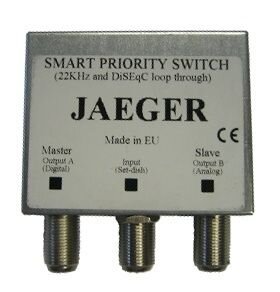
Has anyone in this hemisphere tried out a smart priority switch like this one:

PULSAT.COM - JAEGER SMART PRIORITY SWITCH - SATELLITE TV MOTORS & SWITCHES#

I found the following two descriptions:
(1) Allows you to use either one of two satellite TV receivers with only on LNB (dish) connection. Example: Connect a Freesat box as master and a Sky Digibox as slave. (The Sky box leaves the LNB powered all the time, so can't be connected as master.) When the Freesat box is in standby, the Sky box takes over. Can also be used with an analogue or Digital FTA satellite TV receiver.

(2) The Global SMART switch has one port as the priority output. When this receiver is turned on, LNB control is taken from this receiver. If the priority receiver is turned off, the other receiver takes control of the LNB. Both receivers can watch channels simultaneously from the LNB, but only if they require the same polarity and band.
It seems to me that this would be useful if you had two receivers and the one connected to the master connection could be turned off when not in use.

It appears that the master would normally control the motor (and polarization) if it was powered on BUT the slave would control the motor if the master was turned off.
 
I see what you mean: DPP44 switch may tell this PI bugger under heavy load to switch between 2 wire sets coming from its PA. We cut 28V wire set - and we're done. It may not be the case however: some companies call their PA an "Auto switching transformer", meaning it has some brain of its own, which we can also cut in half if needed.

These are possible scenarios, but there are others. My intuition is that it would not switch to the higher voltage because of a heavy load, but instead might have some means of detecting whether there was a DPP44 switch present. In that case it might send 28V. If "misconnected" to something else, it could fall back to 20.5V. The latter is what DN receivers seem to send to LNBs and other DN switches. But this is rank speculation on my part and is only one of several hypotheses I would be evaluating when opening the unit.

Any chance to add an attenuator down the line to drop voltage from 20.5 to 18V without notably affecting DiSEqC commands signal level?

You would not want to use an attenuator for this purpose for a variety of reasons. The proper component would be a voltage regulator. Regardless, 20.5V is probably going to be fine for a motor. It's only 15% over the nominal 18V and I'm sure they've designed in some margin because consumer level receivers will not have strict voltage tolerances. I had to fix my STB because its vertical polarization voltage was so high it would trip all of my switches to horizontal. You still need to be careful because the 20.5V could easily be higher.

If I needed to do something along these lines, I could easily see myself first in line tearing a unit like this apart. But when it comes to power, extra caution is always advised, even in low voltage and current applications such as these.
 
tamuin

This is interesting switch which offers an advantage of using a Slave receiver to control the LNB when a Master receiver is turned Off. When a Slave receiver is connected to the Master as usual using Master's Loop Out port, the Master should stay in Standby to allow switching by the Slave.

The solution discussed here, presumes independent motor control by multiple receivers, and independent power supply to the motor to avoid the receiver's overload and RF noise generated by its power circuit that blocks sensitive signal reception like DVB-S2, which is particularly true when using Sat PC Cards, or a combo of STBs and Sat & USB Card Tuners. The solution also presumes using powered DiSEqC switches to add more LNBs (not shown on the Motor Control Diagram), provide stabilized uninterrupted power supply to all LNBs independently of the receivers to decrease RF noise, improve LNB durability and channel switching speed, and ensure independent switching control by each receiver.

In other words, its a more elaborate kind of setup, we're talking about in contest of using basic in-line components. Thanks for the suggestion.
 

Attachments

  • Jaeger Smart Priority Switch.jpg
    Jaeger Smart Priority Switch.jpg
    12.4 KB · Views: 133
Last edited:
Has anyone in this hemisphere tried out a smart priority switch like this one...

I've never seen this before, but it looks like a very nice find. It could take care of a lot of situations forum members have been struggling with. However it likely does not address the separate issue of running two receivers at the same time, at least not without additional components.
 
Once a test rug is assembled with this PI bugger, is there a way to measure if the motor is turning the dish by drawing power from the bugger, or the power is in fact drawn from the receiver sending DiSEqC commands to the motor, and the PI bugger does nothing unless connected to its own crappy PA instead of a generic 18V PA, or does nothing regardless? :)

Another issue is if using a 3-or-4 way power passing splitter instead of a 2-way splitter to add more receivers to a single motor control line may result in some unforeseen complications?
 
Only a partial solution

I've never seen this before, but it looks like a very nice find. It could take care of a lot of situations forum members have been struggling with. However it likely does not address the separate issue of running two receivers at the same time, at least not without additional components.

Agreed, this certainly does not address everything that is being discussed in this thread (although admittedly I am not clear on exactly what all of the objectives are).

I think that this type of switch is one step up from using the loop out port on a receiver.

If I correctly understand how it works, you should be able to control the motor from the unit hooked up to the master and still be able to watch tv on the slave at the same time, it is just that the motor position and polarity would be controlled by the master (similar to using the loop out port).

Additionally, you should be able to turn off the receiver hooked up to the master connection (say the receiver in the living room) and then the receiver hooked up to the slave connection (say the receiver in the office/bedroom/den) would be able to control the motor and polarity.
 
Along the same lines my DP legacy converters send much closer to 18V of power and also pass DiSEqC commands. If you have a Superdish-style bandstacked LNB, they will handle the frequency conversion of the upper H band to 950-1450 MHz when 18V is applied by any FTA receiver, or pass the lower V band straight through when 13V is applied. This makes using this type of bandstacked LNB look completely like an ordinary switched FTA Ku LNBF and might be nice for multireceiver installations. On eBay they go for next to nothing.

It may be wise to step back a bit from the above assessment.

A few months ago I set up a DN legacy converter for my Pansat 9200HD and spectrum analyzer to make it easier to work with a bunch of bandstacked Superdish FSS LNBs I was setting up on my toroids. At that time DiSEqC commands were passing through it fine. This was only a temporary trick and was subsequently disassembled.

Over the weekend I was making wiring changes to accommodate a soon-to-arrive Shaw Direct receiver that will use DN bandstacked LNBs on one of the toroids. As this receiver will not understand DN bandstacking, I chose a legacy converter for this purpose. Because SD uses a 22 kHz tone to switch satellites I thought the legacy converter would have no problem passing this through. It didn't work. This wasn't a big deal and was quickly fixed by routing the 22 kHz around the converter via a diplexer and a power inserter, but it made me wonder whether the DiSEqC commands were merely leaking through before or whether the converter is blocking continuous tones. I don't want to mislead someone into thinking this works until I get a chance to further test this.

As a non sequitur, I also discovered it is not necessary to plug the legacy converter into an AC outlet if it is not supplying power to the LNBs. The destacking circuit appears to run off the receiver's supplied power.
 
Interesting find about the PC.

I've got a brand new Power Inserter DPP44 set in the mail already and opened both PI and PA. Trying to find high resolution camera to make some closeup pics. Haven't tested it so far, but found that 3 wires come into the PI from PA. No-load voltage btw red and green wires is 20.8VDC, and there's no voltage btw black and any other wire. So I wonder if desoldering black wire would prevent voltage switch to 28VDC under heavy load.

PI supplies voltage only to its OUT port. Still I wonder, what's the best way to measure if any power is drawn from the STB under the load, or the motor draws power only from PI.

Another interesting thing is PI has a couple of tiny wire jumpers inserted in particular holes in the PCB, each in a single hole. There are other similar holes in the PCB, where these jumpers can presumably be inserted. They're not firmly held in the holes if at all, and I wonder what they're for?
 
Last edited:
Shaw Direct receivers can handle band stacked LNBFs, but a more or less standard band stacked LNBF.

I would like to know what makes the DN Bandstacked Ku LNBF different.
 
Status
Please reply by conversation.

Users Who Are Viewing This Thread (Total: 0, Members: 0, Guests: 0)

Who Read This Thread (Total Members: 2)