Finalizing Motor Control Mod with Power Inserter
Pendragon
I haven't seen your post before moving mine.
")
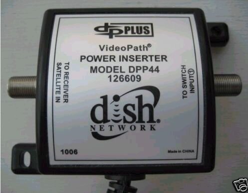
The immediate prompt to ask these questions was to finalize the solution on controlling a single motor from several receivers without modding the motor. We already discussed that a special DPP44 Power Inserter can be used for this, since it passes DiSEqC 2.0 and below commands.
However, I still had some reservations. The Motor is controlled by DiSEqC 1.2 and 1.3 commands requiring no backwards communication towards the receiver to confirm commands execution. However, if the Power Inserter doesn't have a DC Block, can it damage the receivers below the line by backwards voltage? You said, diodes in diplexers and splitters will prevent that unless damaged. It was missing peace of the puzzle.
Again, another missing peace was, if several receivers connected via a splitter to a single Motor power line can damage each other by supplying voltage in reverse. And this concern was largely removed due to diodes employed by the diplexer and splitter to block power in reverse.
Also, if several receivers connected via a power passing splitter can mess up each others brain while sending DiSEqC commands to LNBs, switches and motor. Apparently not because of the above diodes.
Would DC Blocks be helpful in any way to add on any of the lines in the schematics attached?
Another peace is will the motor still draw power from the connected via a splitter receivers, as the Power Inserter appears to act merely as a Voltage Stabilizer having presumably no pass through DC Block? If the motor still draws power from the receiver(s), in what proportion from each?
Did you modify your motor such a way that physically cuts power supply from the receiver on its command port? A weak point to recommend others such mod would be not only the warranty loss, but also that various motor makes have different PCBs, so an average FTA fan would rather damage the motor trying to copy someone else's solution, no matter how good the solution is.
")
Anyway, if you're familiar with Six Sigma quality assurance approach, you know what I mean by all these scenarios. I'm sure, DN and DTV engineers are pretty good at it looking at complex signal delivery systems they created.

 It may possibly supply any voltage within the spec depending on DPP44 Switch & LNB set current power and voltage requirement and voltage drop along the line.
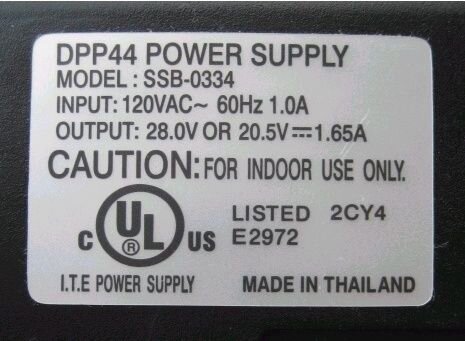
 ) then double posted
