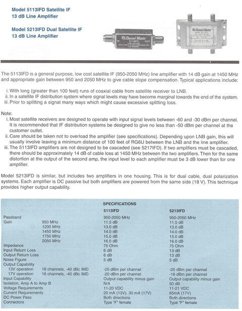
What physics adversely affects use of F-tees to split LNB signal?
Ideally we want all of the LNB's output power that is sent down the coax to be absorbed by the receiver and zero power to be reflected back. For FTA we approximate this by using coax cable with a characteristic impedance of 75 ohms, and matching both ends by using a LNB with an output impedance of 75 ohms and a receiver with an input impedance of 75 ohms. If any of these has a different impedance, some of the energy will be reflected and not all of it absorbed by the load. This will lead to frequency-dependent gain, resonances and other unspeakable horrors.
Let's say we want to connect two receivers to the LNB. The proper way to do this is through a splitter, which will present a 75 ohm load to the LNB and act as two 75 ohm sources to the two receivers. It can only do this last part by splitting the power into two parts via a transformer so the impedance stays matched.
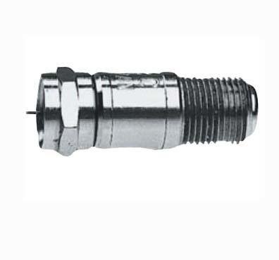
If you instead use a F-tee, to the LNB there will appear to be two 75 ohm loads in parallel at the end of the coax, or effectively 37.5 ohms. This is not 75 ohms and is a very bad impedance match. A lot of power will be reflected and you will have standing waves and nulls all over the place; this will compromise reception drastically if not completely. On the other hand if all the coax is passing is power and/or DiSEqC commands, the frequencies are so low that impedance matching is neither needed nor desirable. In this case F-tees are fine and preferable to splitters.
Sure, many FTA fans would be interested to learn some techniques and workarounds on splitting signal from a single coax downlead when unavoidable.
The obvious way to do this is via bandstacking. If you only have one dish and one LNB, a bandstacking LNB is the practical solution. It is also possible to to stack and destack more than one LNB, perhaps on more than one dish. But things start getting complicated and possibly expensive.
As an example, Dish Network's Dish Pro Plus technology has a switch that can connect four bandstacked LNBs to four dual-tuner receivers (eight independent inputs) using only four coax lines. Let's suppose we hook up the 110, 118.75, 119 and 129W sats to such a switch as follows:
LNB1:
950- 1450 MHz - 110W RHCP
1650-2150 MHz - 110W LHCP
LNB2:
950- 1450 MHz - 118.75W RHCP
1650-2150 MHz - 118.75W LHCP
LNB3:
950- 1450 MHz - 119W RHCP
1650-2150 MHz - 119W LHCP
LNB4:
950- 1450 MHz - 129W RHCP
1650-2150 MHz - 129W LHCP
We connect four dual-tuner receivers A-D to the four switch output ports using DN's special separator to split the signals for each dual tuner input. Let's follow this example:
Receiver A, Tuner 1 wants 119W RHCP
Receiver A, Tuner 2 wants 110W LHCP
Receiver B, Tuner 1 wants 119W LHCP
Receiver B, Tuner 2 wants 129W RHCP
This is what the switch sends down the two cables:
Receiver A:
950- 1450 MHz - 119W RHCP
1650-2150 MHz - 110W LHCP
Receiver B:
950- 1450 MHz - 119W LHCP
1650-2150 MHz - 129W RHCP
For Receiver A, the switch simply picks off the lower band of the 119W LNB and the upper band of the 110W LNB and combines them at the switch output. For Receiver B, the switch has to downconvert the upper band of the 119W LNB to the lower band and the reverse for the 129W LNB. Straightforward, but a nifty trick.
This is a theoretical solution to your problem, but there is a catch: you would have to figure out how DN commands the switch and replicate this somehow. You would also have to use something like Superdish FSS LNBs that follow DN's DSS stacking schemes. Both of these issues could be overcome with skills and/or money. The basic parts are cheap and readily available.
Another choice would be to set up at least one 4x4 or 4x8 multiswitch on the roof plus additional DiSEqC switches if you had more LNBs than the multiswitch could accommodate. This would interface to a stacker on the roof and a destacker inside the house with one coax cable connecting the two. The twist is you would have to engineer a commanding interface to take polarization/22 kHz and DiSEqC commands from two receivers and mux these onto the coax in the house, split them off and recombine them with the signal lines on the LNB side of the stacker on the roof. This is doable and could be overcome with skills and money. Some of these parts are costly and the interfaces would require custom electronics.
Technically either approach could be made to work with sufficient investment. They are not something a novice should ever consider on their own. In most cases extolling the virtues of a hole saw to the proper authorities would be the easiest path to take. But sometimes the highest courts offer no further appeal and one is left with a Hobson's choice. That is what I have described. Do not consider this an endorsement.

 : And learn from what gets revealed (the guts) along the way. That affects future plans a lot - knowledge usually does. I think, we're all trying to do the same thing here, each by own means. This site gets a lot richer in content every day - don't you think? Aren't some politicians prefer to play underachiever - why would they?
 ")
")