Televes Avant-X Programmable 4 input distribution amp

videobruce

SatelliteGuys Family
Original poster
Sep 21, 2003
77
4
I've been working with Televes, both here in Aurora Colorado and in Santiago, Spain as to my situation which is unique to them also.
Simply put, I have stations from 7 and 55 miles away in basically the same compass direction with a difference of 40db which even with channel traps, the problem is still there.
Their Avant-X device which I bought from Ness Electronics whom I recommend very highly, seems to be a possible solution.

Televes (US);
AVANT X programmable multiband amplifier for terrestrial signals, with AutoLTE
Ness Electronics;
Televes Avant X 532180 Multiband amplifier

ASuite software;
https://www.televes.com/us/software?busca=asuite
That requires Java RE v1.7.0 either x86 or x64 v1.7.0.51 from January 2014 actual version
Installed program reports to be 118MB. Actual folder is 139MB
64bit;
Java Runtime Environment (64-bit)
32bit;
Java Runtime Environment (32-bit)

It's surely not for everyone. One needs to know their reception area well, not just where everything is, but just what the signal strengths are. You won't know that by some 'lame' indicator on a TV or outboard tuner/DVR. But, that is another topic.
From two separate documents from Televes, below is a list of features and a brief configuration;
-------------------------------------------------------------------------------------------------------------------------------------------------------------------------------
Features:

Digital processing implemented on terrestrial TV signals
Up to 32 individually programmable filters: single channel digital filtering, adjacent channels (1 to 4 channels)
Output channels can be frequency shifted to any unassigned channel included other bands
Output level is adjustable between 30-55dBmV. Equalization slope up to 8 dB can be programmed at the output.
Automatic signal adjustment in each filter (AGC): and output signal manual regulation (+- 3db)
Digital filters with high selectivity: 30dB rejection (@ 1MHz)
AutoLTE: automatic adaptation of filters, depending on the LTE signal type (CH36/CH51)
CATV input range; 54-1220MHz equalization between 0-18dB. The output level is 55dBmV.
SAW filters (Surface Acoustic Wave) against LTE interference, with the best selectivity and stability
TForce Technology: terrestrial signal level always stable and adapted to its optimum value
Storage multiple setup configurations, allows user to transfer data to other AVANT X units
Zamak chassis provides high RF shielding
Configuration and adjustment using ASuite application for Windows or Android.
Powering of preamps or BOSS (antenna) system
LED indicators displaying power and adjustment status
Easy-to-replace proprietary power supply
FM input when enabled, will be amplified and its output level set to 10 dB below the lowest-level UHF channel (taking into account the equalization slope).
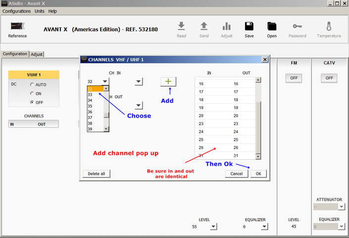
Filters can be tuned to any VHF & UHF channel, its bandwidth can comprise between 1 to 4 channels. The arrangement of the 32 filters is configurable based on the number of channels present on each TV input
ASuite for PC or tablet and Android smartphone, via USB connection (Micro B cable included): A configuration can be defined and stored even without being connected to the multiband amplifier to retrieve it later.
The READJUST button on the unit (short press), will readjust the stored configuration values. A manual adjustment can be performed to the gain +/- 3db in the software.

Configuration and adjustment
Through the PCT programmer unit: select the appropriate parameters for the installation (channels, output level, equalization slope…) and press the ∎ button (long press) which saves the configuration and starts the setting. If programming is done before installation, with the removal of the programmer the process is avoided but the configuration is recorded for later adjustment..
Through the "READJUST" button starts the process of setting the unit with the configuration previously stored by the programmer or the application.
Inputs and outputs must be active for the correct setting of the unit.
During the adjustment process, the green LED remains ON and in case of a level error the red LED will light up.

IMPORTANT WARNING: The Avant X unit ships with a 75 ohm terminator load connected to the TV+CATV output. It is important to make sure that this load remains connected to the TV+CATV output during the adjustment process. The Avant X adjusts the gain of the filters by measuring the level detected at the main TV+CATV output and it needs to be loaded for the reading to be accurate. If the TV+CATV output is not terminated during the adjustment process, mismatches would occur and the results of the adjustment will not be satisfactory.
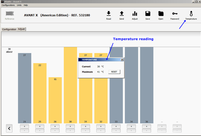
If the adjustment screen shows any bars falling short of the desired programmed in one or several programmed filters, that’s indicative of the corresponding input RF signal being lower than the minimum input value required (-20 dBmV ). In this case, it can not be guaranteed they will function properly through the Avant X and these channels may be impaired with errors.
-------------------------------------------------------------------------------------------------------------------------------------------------------------

_Televes Avant X  ports.jpg
 
  • Like
Reactions: primestar31
The conversations I have had between the three of us have enlightened all of us. There are details that really aren't documented in the very limited 'quick guide' Televes provides. Which brings me to here.
Below are comments from Javier Runano General manager for Telves US and Justo Rodal in Santiago, Spain describing the unit and it's setup.
----------------------------------------------------------------------------------------------------------------------
Javier Ruano
General Manager
Televes USA Norfolk Tech Center
16596 E. 2nd Avenue Aurora, CO 80011

Like any other processing device the Avant has certain dynamic range per filter. It is able to adjust and equalize incoming signals between -20dBmV to 40dBmV to a programmed output level between 30dBmV and 55dBmV (or 75dB margin). Outside of that input range there will be cases where the agile filter programmed for a particular channel or cluster may not have enough gain or attenuation available to bring the channel to the programmed output level. After the automatic level adjustment has been completed, the "adjust" tab allows for a +/-3dB gain adjustment of each individual filter.

It is possible in some scenarios that a fringe signal which is able to marginally be decoded when fed directly to a tuner may perform worse after processing, by the Avant or other device. This is entirely normal as indicated by a user earlier in this thread. Any RF processing of a very fringe signal is not going to improve it's quality. The main advantage of the Avant is to be able to individually process channels coming from up to four different antennas/markets/directions and provide a way to distribute them on a single wire combining them filtered, well balanced and amplified, avoiding co-channel interference and multipath, for further distribution. This is not possible by directly combining the antennas or without an elaborate processing headend. Like in any processing system, the incoming signals need to meet certain specifications.

It is important to note that during the adjustment process the main TV+CATV output be loaded with a 75 ohm termination load. The reason for this is that when the unit is adjusting the gain of each individual programmed filter, it reads the level on that output, and if not terminated, there will be a mismatch and the read value won't be correct, and neither will the filter adjustment as a consequence. During that process, the input signals need to be connected as well, of course. Best practices dictate for any unused ports to be terminated anyway.

Another common configuration mistake is for users to program filters in empty channel locations "just in case" something comes in. This should not be done because the Avant X will maximize the gain of that filter during adjustment, only to add noise to the aggregated signal. The Avant X is intended to acquire existing signals from a set of antennas, and process, balance, and combine them in the best way possible on a compact headend solution. The Avant features an FM input that will be adjusted according to the output level programmed in the unit, and a CATV mix input for when it is used to inject OTA channels in an existing cable distribution.

The North America version of the Avant X, P/N 532180, does not have automatic channel scan. It does require to manually program the channels or clusters desired per input on A-Suite or using the Televes handheld programmer.

Once the unit has been programmed and adjusted, it will establish a set of filters per input, and reject everything else, so if a new multiplex becomes available, yes, a filter will need to be programmed for that channel on the corresponding input, the unit readjusted, and any downstream tuners to be re-scanned if needed.

In a nutshell the Avant X is a filter > processor > amplifier. It allows the filtering of up to 32 individual channels or clusters coming off of four different antennas, and processing them to any frequencies desired, equalize the levels, and provide a programmed output level which is maintained over time. There are a number of applications for this feature set, for example to be able to ingest, filter, equalize and combine content from different markets/antennas in a clean fashion over a single coax feed. Since the Avant also allows to frequency-shift incoming carriers, an operator can receive same RF channels from different markets without co-channel interference.

The output level in the Avant X is programmable between 30dBmV and 55dBmV, and also a slope setting is available for larger cable distributions, such an MDU for example. The higher values will likely be too strong in many residential settings, so the Avant also features a -20dB output, on which the programmed value will range between 10dBmV and 35dBmV. So in practice, the output level can be adjusted between 10dBmV and 55dBmV, enough range to cover a wide variety of distribution scenarios.

The AVANTx has 4 independent input preamp stages (wideband up to 608 MHz) and then the set of 32 filters which are programmable with the different wanted channels. If a channel is blocked, it enters the input preamp, but it is blocked in the filters and it is not present in the output wideband amplifier, where all the signals coming from the 32 filters are boosted altogether.

The main CATV+TV output is the mixed output for the CATV mix input and what comes from the antenna side of the Avant. The way the Avant adjusts the filters is by reading the power level there as it goes through the frequencies and adjusts each filter width and gain. For this reading to be accurate and the adjustment to be satisfactory this output needs to be correctly adapted and loaded with a 75 ohm load, otherwise there will be impedance mismatches, the power reading will fluctuate wildly and the filters will be totally unadjusted.
-------------------------------------------------------------------------------------------------------------

Attached is my "ASuite Custom User Guide". It is in OpenOffice format .odt which will open in Office if you use that.
 

Attachments

  • Televes Avant-X ASuite Custom User Guide.txt
    887 KB · Views: 242
Specifics;
The AVANTx has 4 independent input preamp stages (wideband up to 608 MHz) and then the set of 32 filters which are programmable with the different wanted channels. If a channel is blocked, it enters the input preamp, but it is blocked in the filters and it is not present in the output wideband amplifier, where all the signals coming from the 32 filters are boosted altogether.

The main CATV+TV output is the mixed output for the CATV mix input and what comes from the antenna side of the Avant. The way the Avant adjusts the filters is by reading the power level there as it goes through the frequencies and adjusts each filter width and gain. For this reading to be accurate and the adjustment to be satisfactory this output needs to be correctly adapted and loaded with a 75 ohm load, otherwise there will be impedance mismatches, the power reading will fluctuate wildly and the filters will be totally unadjusted.

My question;
How can the CATV be used with ATSC since they are two different modulations AND two different frequency tables?? IOW's no North American tuner would or could work.
Reply;
The CATV input could add locally generated content modulated in ATSC via encoders.
There is a different version of the Avant X we make for a very large hotel integrator that allows for the incoming OTA 8VSB carriers to be frequency shifted to QAM center frequencies. By having both the QAM and the 8VSB located in CATV frequencies, commercial TV tuners will pick up both and work.

My observation;
Regarding reassigning stations to other physical channel numbers.
I see a possible problem regarding devices when using outside party 'Guide data'. Namely TiVo recorders. Rovi (that owns TiVo and also supplies the data for their 'Guide') has their 'system' programmed to expect stations to be on predefined physical channel numbers. During the 'repack' when everything was in 'disorder', stations that 'moved' earlier than expected the 'Guide' data did not show under the new physical channel number. It still did show on the old allocation, but not under the new assignment.
IOW's you could not record a program on that channel without manually entering in the channel number, start & stop times, AKA 'VCR' style. They changed their regional data to now include stations in the market you are in. Of course there are many mistakes in this and many stations would be out of range for most owners given the lack of decent outdoor antenna(s) or just being in a poor location. I guess to make things easier for 'Joe SixPack' where an antenna scan almost isn't necessary (but still required).
Moving the station to a different physical channel number I would expect would do the same thing.

Here is the eight page "ASuite Custom User Guide"

00 ASuite Open-Select Device page.png01 Select Reference.png03 Config output adj.png02 Adjust device not connected.png04b ASuite Add Channel.png05 Channel list complete.png06 Adjusting channel.png07 ASuite Save Config.png08 12-10-2020 Adjust 1.png08b 12-10-2020 Adjust 2.png09 ASuite Tempurture readout.png10 ASuite Remove channel labeled.png10a ASuite SW & FW versions.png12 ASuite & java Processes running-crop-vert.jpg
 

Attachments

  • 04 Add channels.png
    04 Add channels.png
    26.2 KB · Views: 207
  • 09 ASuite Tempurture readout.png
    09 ASuite Tempurture readout.png
    16.4 KB · Views: 203
Last edited:
_Avant X block diagram labeled.jpg

------------------------------------------------------------------------------------------------------
Taken from Justo Buffalo-Toronto plan
by Justo Rodal Santiago, Spain

The AVANTx can accept signals in its input ranging from -40 dBmV to +20 dBmV, that is to say, 60 dB. The block diagram of the AVANTx, which is depicted as follows, is helpful to understand why the balancing cannot be achieved.

The AVANTx has 4 inputs. Each one of the inputs has a first block of analog filtering, VHF high&low
and UHF, after which a high margin amplifier prepares the whole set of received signals to the digital
filtering block. After these 4 amplifiers, and before the digital filters, there are 4 Analog to Digital
Converters (ADCs), one per amplifier, that give off the digital samples of each input to the digital filtering block.

This digital filtering block encompasses 32 filters, which are programmed by the user depending on the channel map in the location. The AVANTx can operate without channel conversion (i.e. same output as input channel) or performing channel conversion, moving the output channel to a different frequency. The digital filters bandwidth depends on the presence/absence of adjacent channels to the wanted channel. If there aren’t channels, this bandwidth is wider.

The problem of this schema is that the AVANTx won’t be able to cope with input imbalances higher
than 30 dB in the same input1, because input 1 receives signals from Buffalo and from Toronto. Due to the high level of the signals received from Buffalo, the amplifier attenuates input 1 instead of boosting, not to overwhelm the ADC. That makes that the low level signals received from Toronto are attenuated, which makes the balancing of the whole set more difficult.

Ideally, to solve the problem, we should be receiving the signals coming from NW from two different
antennas, separating Buffalo and Toronto. However, this may not be possible, as the directivity of these antennas should have to be extremely good as the beam width of reception is very narrow.

The problem of this scheme is that the AVANTx won’t be able to cope with input imbalances higher
than 30 dB in the same input1, because input 1 receives signals from Buffalo and from Toronto. Due to the high level of the signals received from Buffalo, the amplifier attenuates input 1 instead of boosting, not to overwhelm the ADC. That makes that the low level signals received from Toronto are attenuated, which makes the balancing of the whole set more difficult.

Ideally, to solve the problem, we should be receiving the signals coming from NW from two different
antennas, separating Buffalo and Toronto. However, this may not be possible, as the directivity of these antennas should have to be extremely good as the beam width of reception is very narrow.

The solution to use traps to attenuate individual signals in channels 15, 16, 31 and 32 seems therefore the only option reasonable not to override the input ADC of the AVANTx. However, the frequency response of the traps (picture below) added to the fact that channels 15 and 16 are adjacent to channels 14 and 17 coming with low levels from Toronto affect the level of these latter, as the trap is not strictly speaking narrow band.

Therefore, the use of traps attenuates effectively the higher level channels, yet impairs the adjacent
ones. In the scenario we have, the trap in channels 31 and 32 would be useful, impairing channel 30,
whilst the use of traps in channel 15 and 16 impairs channel 14 and 17 from Toronto. There is a
channel 33 in use, yet received by the second antenna pointing to SW. Therefore it would not be
affected by the use of the trap 31-32, provided that this second antenna uses a different input of the
AVANTx to process the channels.
-----------------------------------------------------------------------------------------------------------
_My antenna 3 input config.jpg


Input 1 in AVANTx would process the channels from Buffalo with the highest received levels. If needed, an attenuator could be placed in order not to override AVANTx input, as the level could reach the maximum of +20 dBmV. The channels from Toronto are disregarded in this input.

Input 2 in AVANTx would process the channels from Toronto. It is necessary to attenuate the levels of
the channels 15,16, 31 and 32 by using the traps. If possible, the frequency response of the traps could be modified in order to achieve a minimum impair in the adjacent channels. However, channel 30 is extremely difficult to process, as the imbalance regarding nearby channels is too high.

Input 3 in AVANTX would process the channels from Buffalo received by Antenna 2.
 
Last edited:
Problems
The outstanding problem is differential in signal level. That was addressed here in one of his emails;
---------------------------------------------------------------------------
My point;
From page 5 of the “Product Sheet”;
Recommended input range....dBmV.. -20…40
Gain regulation................... ....dB......... 0…30 (auto)
That is not the clear, the term “Input” is not used in the line for "Gain regulation", assuming that line is the difference issue.

His response;
What the AVANTx cannot do is to balance a difference of 30-35 dB IN CASE OF ADJACENT CHANNELS
. If the channels are not adjacent, there is no problem. The reason is because the filter, albeit digital, takes a vestige of the upper and lower channel. If the level is very high, spikes appear, as you saw in your graphs. See below channel 17 with a peak which is a vestige of high level channel 16. Notice that the level of channel 17 is lower than 18, 19 and 20, yet the power detected is the same, because of the peak of adjacent channel 16.
------------------------------------------------------------------------

The 2nd problem is the width of their electronic channel filters.
On adjacent channels, the width is the narrowest of the two widths presently available. Take a look at these attachments of ch 15 & 16 and the text in them. Note, This is the 'vestige' (residue, so to speak) that is 'left over' from the carriers of those two channels.
I realize there is a trade off and a 'balancing act' of sorts as to the width of those filters. Normally I'm sure it is proper. In this case I don't believe it is.

BTW, look at the last attachment. That shows the level differences here.

07 3 inputs no 16, no traps 355deg labeled.png
11 15,16 w traps no ch 16 filter question.png
UHF 8 bay 01.png
 
1. Filter bandwidth:
The Avant-X is based on European TV channels which is 8 MHz derived from PAL & SECAM systems (with some being 7 MHz).
This can cause problems with adjacent channels here that are overpowering the wanted channel due to (what I call) 'leftovers' that aren't attenuated enough affecting the neighboring channel.. Level differences over say, 25-30 db can cause issues depending of the specific situation.

https://www.britannica.com/technolog...h-requirements (scroll to bottom of the page)

Take a look at the attachment (ch 16 enabled, no other, TG scan);
single ch 16 internal X filter width.png


2. Non-controllable AGC:
I was never a fan of 'auto' anything, especially when it comes to electronics. There is always a compromise. While it can work, many times it doesn't, or doesn't work correctly. Not having control can lead to other problems. ALC, AGC, for audio or video, Auto-Iris, Auto White Balance Auto exposure for cameras (film or video) and AGC circuits in RF amplifiers. It's all a compromise and how the circuit was programmed.
Reducing some levels while amplifying others to 'flatten out' the spectrum sounds good on paper, but if that includes cranking a weaker station excessively or increasing a channel that was 'blocked with that 'left over' present can cause issues.
While this has a +_ 3db level adjustment range, it is better than nothing, but I don't feel that is adequate enough. Frankly, a 'off' setting would be nice.
 
Last edited by a moderator:
To add to the above post and clarify further;

From my experience tiring different DA's (distribution maps) in place of my long term Winegard DA1018 DA (18db gain, adjustable), for example, Winegard's 36db version was way too much to handle the excessively strong signals that I have had to deal with for well over 25 years.
First with analog, then digital, now with a UHF spectrum that was reduced a THIRD time (originally 82, then 68, then 50, now only 35 channels) no thanks to the "toy phone" industry, cramming everything much closer together.
Single channel tunable traps (filters if you prefer) were the only solution. To be clear, this has to do with stations coming from the same direction within say +,-20 or so degrees and close and far distances.

Even at the lowest output which is 30db, with the three 'problem' stations (as I call them) still overload the Avant-X with my custom traps. Without the traps , I loose at least five channels. Period! The signal is there, but numerous factors prevent tuners (TV's) from locking on to them.
If that was reduced down to 20db, I would be willing to bet most of that issue would go away.
Before anyone one suggests adding a 10db 'pad', that just defeats the purpose of this in the 1st place. And just using the 'test port' doesn't solve the problem either, since the 'damage' is already done before the output.

I have proved it more than once in testing , without my custom traps, this would of been completely un-usable, as I stated earlier mostly due to excessive gain and filter width. I LOOSE channels including one VHF (which I can only guess it's because of noise, but that is just an educated guess), not because of any adjacent channels or excessive signal strength. That alone is almost deal killing as those custom traps were almost the cost of the Avant-X.

When I went back to my existing setup (the Winegard DA), two of the stations that were missing, locked back in. That was enough and the two months of fighting with this to get it to work. It was returned. I just couldn't justify the cost in spite of the time I put into this.

It just isn't the 'silver bullet'.
But, I'm sure under more favorable conditions it could be. The only way to know is to try it.;)

Below are pics of the testing, then the final setup in the attic, (not a crawl space) and a scan of the 'traps' that allow to Winegard DA-1018 DA to work where the Avant-X didn't. (The double trace was the traps, flipping the order to see if that mattered, the 'dips' are ch 15 & 16 then 31 & 32)

Anant-X Head End small.JPGWinegard MATV Head End 02-21 small.JPGCan 16-32 & 32-16 traces.png
 
Last edited:
One thing from looking at specs for the different dist. amps they have is mention of DC output to the antenna for a mast preamp. Very important for long runs to the indoor amp. But I didn't see anything really mentioned if the power was switchable in software.
A folded dipole antenna would provide a shorted active element presented at the coax.
And therefore a shorted power supply at the dist. amp.
As would a matching transformer for either a yagi or log periodic antenna. Or any antenna used with a match.
What input do you have for this?
Also. From another comparison post here the specs for their devices show a high noise floor.
For example. A 0.4 dB for one amp vs ~4 dB for the Televes products.
And comparison for one member here who has actually tested a Televes mast preamp vs another has said the Televes provides a dead channel where the 0.4 dB noise figure amp provides a solid watchable picture.
What is your input to this?
 
The preamp power is switchable. Take a look at my guide and the input table channel assignments.
AFA experiance with preamps, I've never used any since I'm not a beleivere in them due to overload issues with strong signals. My runs from the antennas are shorter than 25' before they get to where I can have a 'handle' on them, so that isn't a issue here.
 
Some of the statements throughout this discussion are not correct. The Avant X P/N 532180 does not use 8MHz filtering. That would be useless in the North American market. It does use 6MHz filters, actually dynamically optimized for adjacent channels.

The main issue in this installation is the Avant X can balance 60dB worth of mismatch between carriers, except in the case of strictly adjacent RF carriers in the same input, in which the maximum level correction is limited to 30dB. This use case falls outside of the unit's specs.
 
Some of the statements throughout this discussion are not correct. The Avant X P/N 532180 does not use 8MHz filtering. That would be useless in the North American market. It does use 6MHz filters, actually dynamically optimized for adjacent channels.
Long story short;
After having a long and productive telephone conversation with Dylan from 'WNY Over The Air' regarding other matters and then this product and the detailed, documented problems with the unit I had (it was returned). We came to the conclusion it was this specific unit that had the problem which was never even suggested to me by Televes !!!

Apparently, I had a unit that had the European filters (8MHz) but loaded with the American firmware (6MHz channels) which would explain everything. Unfortunately, that possibility didn't occur to me or anyone else except for a single post by another individual in another forum which I didn't catch. That was my bad, but I already returned the unit previously at that time.

After spending probably 2 weeks on and off with that, I just couldn't be bothered with going any further since I felt I wasted my time especially considering the very negative response and accusations I received from that company.