And I thought I was into overdoing it That's a lot of soldering to hook up 6 wires and flash one chip. Nicely done! I can see exactly how the chip is wired to the header now. I like how you used the header pins and cables in these projects. I ran across some cheap sources for these components and ordered up a couple of hundred. I'm sure there will be more projects I want to try.
Still waiting for parts. The prototype PCBs I ordered through Amazon never showed. And no tracking on it from China. Fortunately it's only $4. I didn't know Amazon did business like that. I ordered some more off EBay, with tracking from China it will be here soon
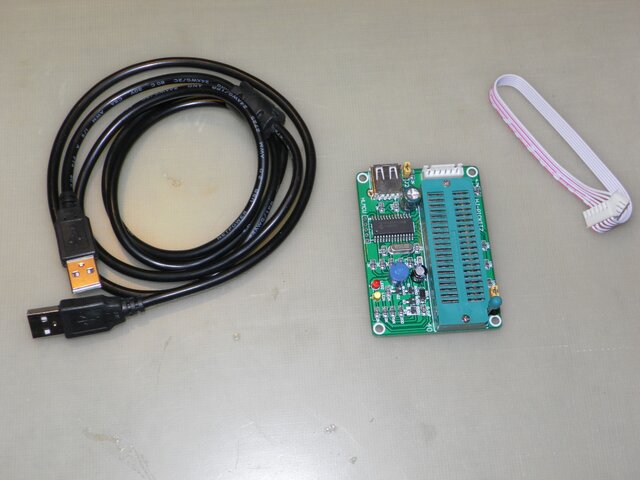
Hmm... pictures are not going to thumbnails... Well There is some progress. The programmer worked like a charm. Too easy LOL. Tomorrow I will install it and see how bad I screwed it up
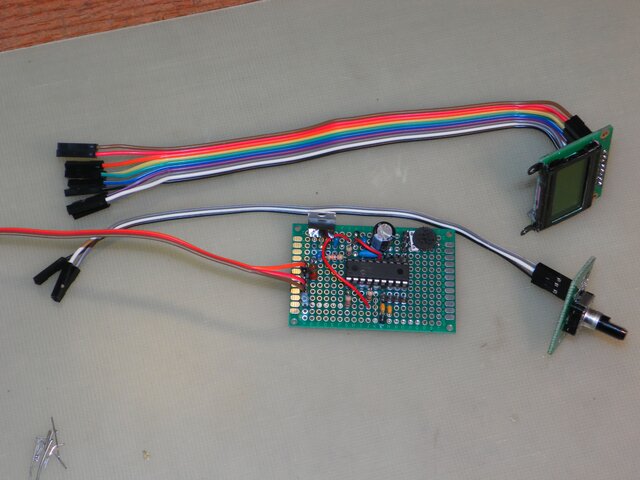
I finished the assembly of the circuit. Using a 12v PS I bench tested the circuit and it looks good. Just what I expected to see. The encoder changes the skew angle on the display. I'm amazed. With my skills (or lack there of) this must be a robust little circuit @NOQBH . I thank you for the fun and knowledge you have provided me. I'll install this in the controller and do some more testing.
And I broke it! LOL Installed it in the case and hooked up the screen backwards. Screen now displays random junk. What do you think? Killed the screen or corrupted the PIC? Hate it when you crash on turn 4 on the last lap.
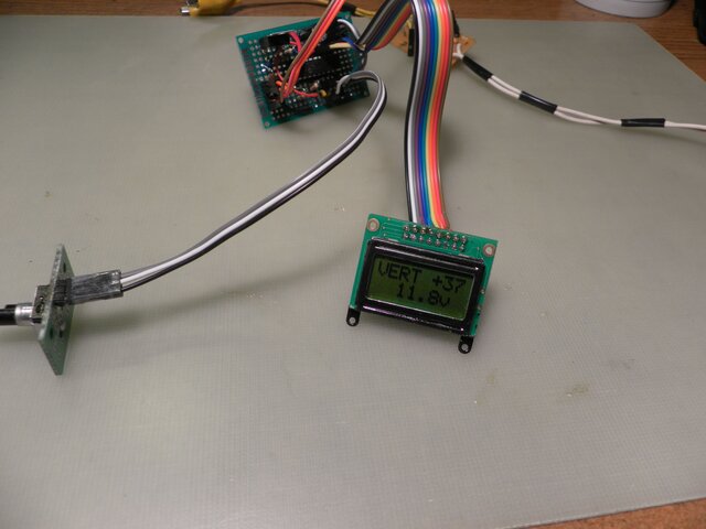
A new display is coming And that is all I appear to have broke. I ran a full function test with a polarotor motor on a Corotor II. Everything works as described I split the power needs of the unit. The logic circuit runs off LNB power and the Polarotor motor runs off power from the VBox. When you shut down the receiver the polarotor defaults to Vertical.
New developments. I've been thinking about that display and looking it over. I noticed there is a jumper configuration chart on the back of the display. It indicates two ways to enable the backlight which this doesn't have. I got to looking at the display that does have a backlight. The only visual difference between the two was that the backlit one had the jumpers soldered. That made me think that maybe there was a backlight in the one and I just needed to solder the jumpers for it. Couldn't hurt to try. I already messed it up by plugging it in backwards right? Well I was certainly shocked when I plugged it in and although here was no backlight the unit was functioning perfectly. huh? OK then! A little more investigating led to the real problem. Poor connections. Break out the "Stabilant-22" and no more problem I that stuff. I didn't hurt the display after all.
The backlight can made to run on a separate power circuit via pins 15 & 16, or you make it come on when the display is powered via pins 1 & 2. there are jumpers to enable all 4 pins. The backlit one comes with pins 15 & 16 enabled. Since I have a 5v source in the VBox it would be a simple thing to put a switch on the back to turn on the backlight
What we need now is a add-on circuit to insert LNB power 18v - 24v and have less signal loss than a separate device with coax connections.
The control has some interesting properties. The skew adjust only affects the polarity you are on. When you power down the circuit the encoder resets to +45/-45 no matter the position of the knob. Recommend not using a knob that is indexed or has a pointer.
The control has some interesting properties. The skew adjust only affects the polarity you are on. When you power down the circuit the encoder resets to +45/-45 no matter the position of the knob. Recommend not using a knob that is indexed or has a pointer.
It's been awhile since I wrote the program so I had to check. The unit doesn't store the last skew when turned off because that part doesn't have non volatile memory (EEPROM).
Most likely because my system stays on 24/7, I just turn off the tele.


") That's a lot of soldering to hook up 6 wires and flash one chip. Nicely done! I can see exactly how the chip is wired to the header now. I like how you used the header pins and cables in these projects. I ran across some cheap sources for these components and ordered up a couple of hundred. I'm sure there will be more projects I want to try.
That's a lot of soldering to hook up 6 wires and flash one chip. Nicely done! I can see exactly how the chip is wired to the header now. I like how you used the header pins and cables in these projects. I ran across some cheap sources for these components and ordered up a couple of hundred. I'm sure there will be more projects I want to try.
")
 And no tracking on it from China. Fortunately it's only $4. I didn't know Amazon did business like that. I ordered some more off EBay, with tracking from China
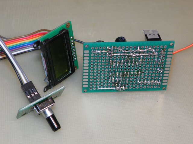


 that stuff. I didn't hurt the display after all.
