

Social Feed
Hi guys,
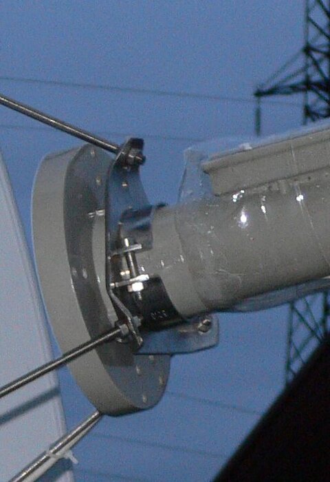
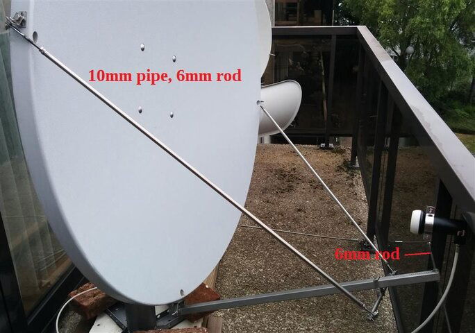
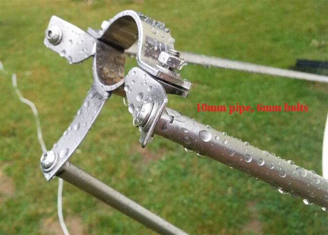
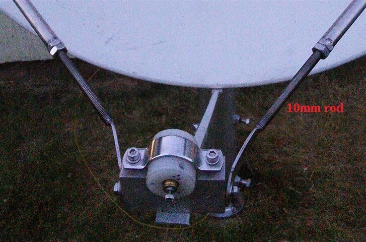
I'm working on some replacement "arms" to hold my scalar ring and LNBF on a 10 foot dish. The old arms are weak and rusting out badly.
Previously when I put the dish up, I simply assembled everything, and adjusted the LNBF in / out of the scalar ring, but I didn't pay attention to the f/D ratio because I didn't measure and calculate it. This time I'd like to do it a little better by measuring things and getting it right. I've measured the dish with a string test (fishing line works well), and come up with a f/D ratio of approximately 0.34 and a focal length of approximately 41 inches.
Knowing that the focal length is ~41 inches, where do I place the scalar ring, and the front lip of the LNBF?
From what I understand, the LNBF should tightened on to the scalar ring at the f/D ratio (0.34) first. From there, the front lip of the LNBF with scalar ring should be placed about 1/4 inch closer than the focal length, so 40.75 inches in my case. Once that's correct, I tighten the new "arms" to hold it all in place, adjusting the arms / scalar ring attachment points to get the focal length correct.
Does this make sense? Am I misunderstanding something?
sgs
I'm working on some replacement "arms" to hold my scalar ring and LNBF on a 10 foot dish. The old arms are weak and rusting out badly.
Previously when I put the dish up, I simply assembled everything, and adjusted the LNBF in / out of the scalar ring, but I didn't pay attention to the f/D ratio because I didn't measure and calculate it. This time I'd like to do it a little better by measuring things and getting it right. I've measured the dish with a string test (fishing line works well), and come up with a f/D ratio of approximately 0.34 and a focal length of approximately 41 inches.
Knowing that the focal length is ~41 inches, where do I place the scalar ring, and the front lip of the LNBF?
From what I understand, the LNBF should tightened on to the scalar ring at the f/D ratio (0.34) first. From there, the front lip of the LNBF with scalar ring should be placed about 1/4 inch closer than the focal length, so 40.75 inches in my case. Once that's correct, I tighten the new "arms" to hold it all in place, adjusting the arms / scalar ring attachment points to get the focal length correct.
Does this make sense? Am I misunderstanding something?
sgs
10 Replies
·
3517 views







 The "top edge" could be the flat part of the scalar, but I assume it's the edge with the lip, not the flat back part. Generally that would make sense to me, because we cannot see the markings where the flat back part of the scalar ring is, when installing.


Staff member
HERE TO HELP YOU!
Cutting Edge
Sometimes a thread gets so many posts in it that is can cause issues for the server so that why today we introduce The Song Name Game Part 3!
So let the game continue!
The last song was added by Bobby who posted...
One Meat Ball - Andrews Sisters
CONTINUE ON AND HAVE FUN! WELCOME HOME TO SATELLITEGUYS.US!
Here are the original rules for the game as posted by WebbyDude back in 2006. http://www.satelliteguys.us/threads/68645-Song-Name-Game
Just name a song title and the band who performed it. The next person does the same thing, but needs to list a song title or band name which includes a word from the previous entry. Pick songs from any genre.
Example:
Long Live Rock and Roll -- Rainbow
Rainbow in the Dark -- Dio
Another example:
Ride the Lightning -- Metallica
Lightning Strikes -- Ozzy Osbourne
Get it?
An additional note: we all know that song titles, sometimes, use profane words. Because this is a family friendly website it is advised that you clean up that title up a bit. This is accomplished by using something like sh!t instead of the real word. Thanks....
So let the game continue!
The last song was added by Bobby who posted...
One Meat Ball - Andrews Sisters
CONTINUE ON AND HAVE FUN! WELCOME HOME TO SATELLITEGUYS.US!
Here are the original rules for the game as posted by WebbyDude back in 2006. http://www.satelliteguys.us/threads/68645-Song-Name-Game
Just name a song title and the band who performed it. The next person does the same thing, but needs to list a song title or band name which includes a word from the previous entry. Pick songs from any genre.
Example:
Long Live Rock and Roll -- Rainbow
Rainbow in the Dark -- Dio
Another example:
Ride the Lightning -- Metallica
Lightning Strikes -- Ozzy Osbourne
Get it?
An additional note: we all know that song titles, sometimes, use profane words. Because this is a family friendly website it is advised that you clean up that title up a bit. This is accomplished by using something like sh!t instead of the real word. Thanks....
68503 Replies
·
2671038 views


For quite a while now, people with a VIP211k have been losing their recordings on their activated external HDDs... even when there's nothing physically wrong with HDD. I believe this is an intentional and underhanded tactic that Dish is pulling in an attempt to force users away from the VIP211k.
They are obviously regretting that they ever let users have a "non-dvr" dvr in the first place. You would think they would be happy charging you a $40 one time fee... and then be happy letting the customer be the one responsible for HDD failures.
Dish clearly hates the 211k bitter-clingers. This recording deletion problem is intentional (IMO), and I think it is just one more tool that they are using. Hopper and a 2-year agreement... that's what they want you to have. Think about that... a 2-year agreement... with a company $30 Billion in debt (that's with a B). What happens when all that debt causes them to drop the channel that may have been your whole reason for having Dish in the first place? Guess who's stuck with a service that no longer suits their needs... for the remainder of the 2-year agreement.
On top of that, they don't want you to install it yourself. I purchased and installed all my equipment myself. That used to be common. Now, they lie to me and tell me that my dish must be updated to use a Hopper. Funny thing is... they don't even know what dish I have because they didn't install it, and I didn't tell them. If you ask what type of dish/LNBs the hopper needs... good luck getting an answer. All they know is that whatever you have needs to be upgraded by an installer.
It is quite apparent to me that they care much more about staying in their box, than they do working with the customer. That's too bad, because it hasn't always been that way. It's like they are totally unaware of the current business environment that they are trying to compete in.
I have been a customer since 2010. I will be cancelling my service before the next period. Yeah, I know, my $1,200 a year won't make a difference to them. It just seems like they have forgotten who needs who, especially when you consider the competition in today's streaming world. But hey, they will have succeed in forcing me off the 211k.
They are obviously regretting that they ever let users have a "non-dvr" dvr in the first place. You would think they would be happy charging you a $40 one time fee... and then be happy letting the customer be the one responsible for HDD failures.
Dish clearly hates the 211k bitter-clingers. This recording deletion problem is intentional (IMO), and I think it is just one more tool that they are using. Hopper and a 2-year agreement... that's what they want you to have. Think about that... a 2-year agreement... with a company $30 Billion in debt (that's with a B). What happens when all that debt causes them to drop the channel that may have been your whole reason for having Dish in the first place? Guess who's stuck with a service that no longer suits their needs... for the remainder of the 2-year agreement.
On top of that, they don't want you to install it yourself. I purchased and installed all my equipment myself. That used to be common. Now, they lie to me and tell me that my dish must be updated to use a Hopper. Funny thing is... they don't even know what dish I have because they didn't install it, and I didn't tell them. If you ask what type of dish/LNBs the hopper needs... good luck getting an answer. All they know is that whatever you have needs to be upgraded by an installer.
It is quite apparent to me that they care much more about staying in their box, than they do working with the customer. That's too bad, because it hasn't always been that way. It's like they are totally unaware of the current business environment that they are trying to compete in.
I have been a customer since 2010. I will be cancelling my service before the next period. Yeah, I know, my $1,200 a year won't make a difference to them. It just seems like they have forgotten who needs who, especially when you consider the competition in today's streaming world. But hey, they will have succeed in forcing me off the 211k.
168 Replies
·
7446 views


Pub Member / Supporter
Lifetime Supporter
Has anyone subscribed to NBA League Pass for 2026-27 and try to link their account to NBA.com to stream League Pass? I purchased it for 2026-27, and when I linked, I got a message saying success, but then I receive an error that my linked subscription does not include the preseason games for NBA League Pass. Is that how it has always been? I know satellite doesn't have the preseason games on the NBA League Pass channels, but I thought that I was able to stream the preseason once I linked my account on NBA.com?
2 Replies
·
66 views


Supporting Founder
Really excited for this season with Kentucky having a new coach and some really exciting recruits. Probably won't last long, but here's hoping this season is great.
143 Replies
·
1441 views


For some reason, the satelliteguys.us site is loading a lot slower than usual on both Chrome on my Asus laptop and Safari on my iPhone.
I'm also seeing longer appearances of the blue bar at the top and the "3 blue bars" loading symbol.
Is anyone else also having the same problem? Thanks in advance.
I'm also seeing longer appearances of the blue bar at the top and the "3 blue bars" loading symbol.
Is anyone else also having the same problem? Thanks in advance.
530 Replies
·
18087 views


I thought I would come here and find lots of complaints about the update to the dish anywhere mobile app, but am not seeing any. It used to look just like the desktop webpage. Now you can no longer filter by sports channels or movie channels. Plus that they made it look like a big button telephone and you see fewer channels in the screen which requires more scrolling. Yes I realize you can look at sports then select which sport you want to look at, I just liked being able to see all sporting events in the guide with all other channels being filtered out. Am I alone in the wilderness on this?
7 Replies
·
134 views


Supporting Founder
Pub Member / Supporter
Lifetime Supporter
Apple has finally released their Apple TV 4K with built-in Siri and a microphone so it can respond to your queries even if you don't have the remote. It also increases in price, to $299. I had been planning on updating my current Apple TV 4K streamers, but that's $600 for the two of them, and that's a pass at this point.
At $299, it had better come with 256 GB of Storage, Gigabit (or better) Ethernet, the latest HDMI tech and standards, and one year of free Apple One. But it probably won't…
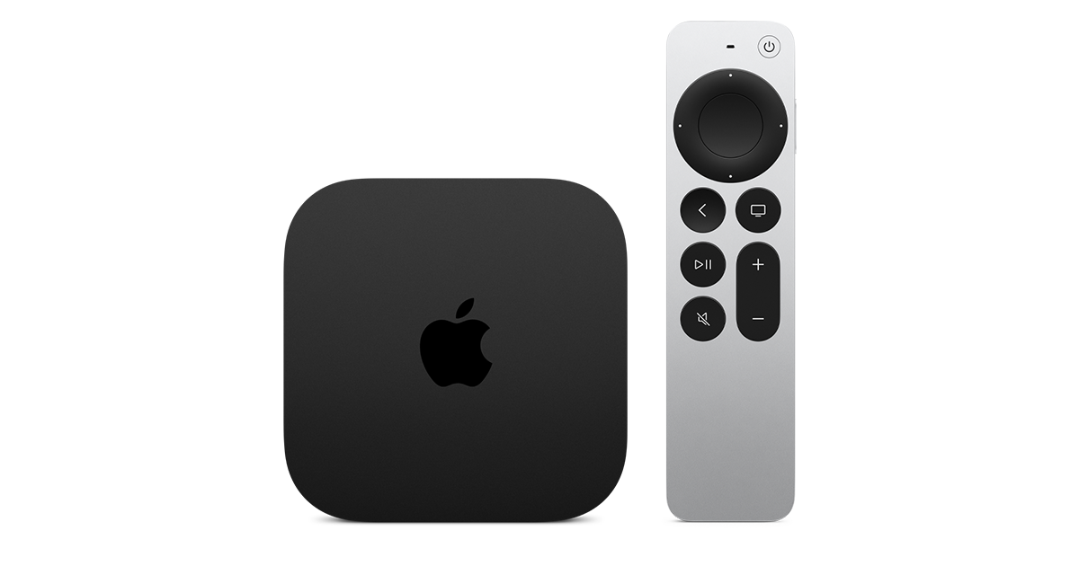
At $299, it had better come with 256 GB of Storage, Gigabit (or better) Ethernet, the latest HDMI tech and standards, and one year of free Apple One. But it probably won't…
Apple TV 4K
Apple TV 4K. New Siri AI and hands-free control. Stunning picture and immersive HomePod surround sound. Works with your Apple and smart home devices.
www.apple.com
20 Replies
·
298 views


 . apple's been making money off of software and not hardware for a while


TWiT Tech Podcast Network
Time for another AWESOME video from the TWIT Network!
View: https://www.youtube.com/watch?v=Y4Edq2eavsQ
Direct YouTube Link - This Week in Space 232
TWIT's Website
TWIT Live Feed
View: https://www.youtube.com/watch?v=Y4Edq2eavsQ
Direct YouTube Link - This Week in Space 232
TWIT's Website
TWIT Live Feed
0 Replies
·
21 views
TWiT Tech Podcast Network
Time for another AWESOME video from the TWIT Network!
View: https://www.youtube.com/shorts/oRVxjGm0qtE
Direct YouTube Link - Tim Cook, Elton John & King Charles: A Royal Tech Event
TWIT's Website
TWIT Live Feed
View: https://www.youtube.com/shorts/oRVxjGm0qtE
Direct YouTube Link - Tim Cook, Elton John & King Charles: A Royal Tech Event
TWIT's Website
TWIT Live Feed
0 Replies
·
17 views