Another Bird View Comes Back To Life!!!

  • WELCOME TO THE NEW SERVER!

    If you are seeing this you are on our new server WELCOME HOME!

    While the new server is online Scott is still working on the backend including the cachine. But the site is usable while the work is being completes!

    Thank you for your patience and again WELCOME HOME!

    CLICK THE X IN THE TOP RIGHT CORNER OF THE BOX TO DISMISS THIS MESSAGE
Status
Please reply by conversation.

NE8E

SatelliteGuys Family
Original poster
Pub Member / Supporter
Dec 19, 2010
35
2
Mid Michigan
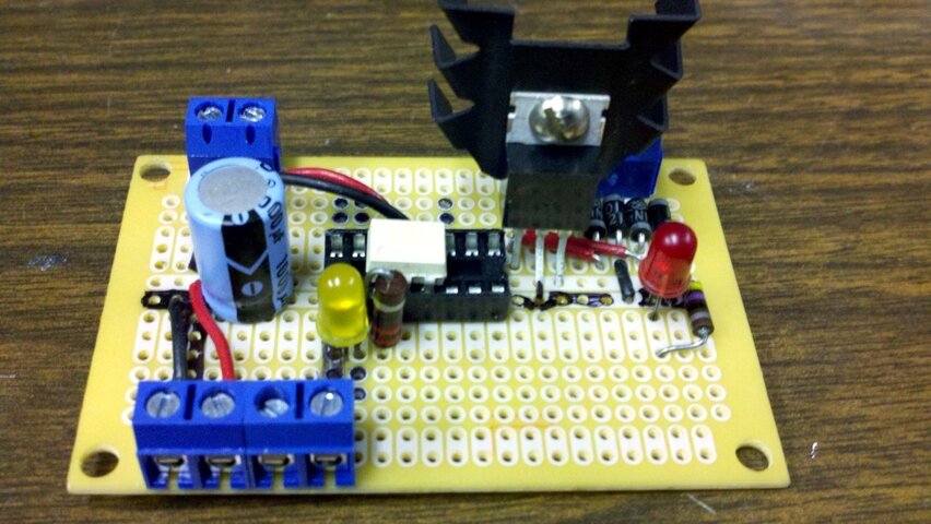
I came up with a simple circuit for running a rotary encoder for higher resolution. I went with a Motorola 8103 Isocoupler because I had several that came out of old IBM Servers. I used 4 1N4001's to make a bridge and a 5 volt regulator so I could tap into any power I found onboard. The large cap is for DC smoothing. The red LED is power, the yellow LED is the pulse. The circuit can handle 1000 pulses per rotation easy, but 48 is working great.

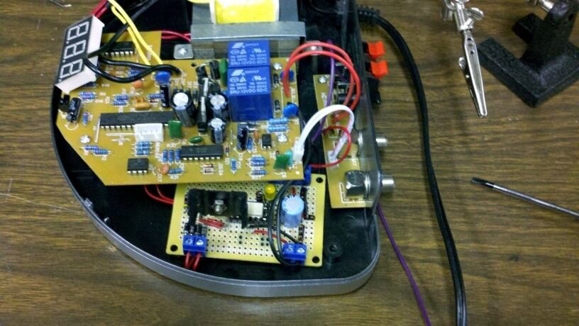
The install: This particular install is in a VBox-X (It also worked in a VBox VII) Inside the VBox-X I found a nice 11V AC right of the transformer. I soldered here for power. The other connections were even easier. I unsoldered the two black signal leads to attach to my board then ran my converted isocoupler output to other circuit board. I ran the 5 volts for the isocoupler to the outside connecions that were no longer needed. This left only one more connection. The pulse signal coming back from the encoder. I ran a 20 AWG stranded from my board right out the opening for the existing signal connection. No new holes in the box, and everything could be put back to perfect original if needed.

One bonus with the VBox-X that the VBox-VII lacked, was the nice tinted display cover. This allows the power and Pulse LED's on the board to show VERY NICELY! Sorry, the camera screwed up that pic. But if you have ever seen the VBox-X, you know exactly what I mean. Below are a picture of the board by itself, and installed in the VBox-X.

I need to thank Satelliteguys.us user "Radio" for trusting me to tinker on the brand new box, for giving my space to tinker, and for buying the parts I needed. Also, a special thanks to users "nicknjen". Nick for the Rotary Encoder idea and for beta testing the circuit all last month, and Jen for patiently allowing the beta test.

If I failed to give enough info on how to do this yourself, I appologize. I will be glad to help with any questions. My friends have been hounding me to write up my projects for years. This is the first one I bothered to write up. Thanks to satelliteguys.us for a place to write it. :eek:

NE8E VBox-X Mod.jpgNE8E Rotary Encoder Board.jpg
 
Very Nice!!! I love seeing people break out the soldering iron. Matter of fact my Weller is sitting here right now.
 
Great project

I couldn't find the icon for the two hands waving a big salute , but that was worth one! If I ever get a birdview I promise to hound you for one of those too!
 
What NE8E hasn't told you, and I've wanted-to, is that a "custom" version of this encoder idea saved my Birdview from becoming just a bird-BATH and he also engineered THAT version with the help of user nicknjen. Seems FTA engineering and enjoyment is growing in my area!

On the grounds of the radio station, my first encoder (which was like the one his solid state relay is designed-for) failed due to having to run it at
a higher voltage to overcome the RF on the line. In fact, the "off" cycle of the pulsing really never was "off", but just showed on test equipment as a reduced voltage, but never went to zero, hence it never shut off completely. This meant the counter was erratic and the results were disappointing, with eventual failure of the smaller rotary encoder.

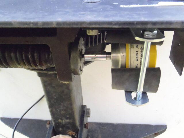
With all the RF floating around, we had to use a higher voltage-tolerant encoder set to only 20 pulses per revolution, in a custom mount on the end of the worm gear outside. Then, inside (wish I had pictures) a metal box houses a mechanical relay, power supply, and leads that go to the V-Box 7. running the higher voltage encoder allowed the RF to be bled off via some diodes, I'm told. (NE8E help me out, here, please if more details are needed)...and, though I'm relying on a mechanical relay mounted nicely to a socket in the metal box, we won the "battle of the RF" and the system is running again. Encoder mounting picture attached. Promise not to laugh, please...but...you'll note the home-made "shock mount" (rubber) that allows minor movement of the encoder should the alignment between the two shafts get off just a bit. Ask any radio engineer...RF is an animal all its own, and tough to beat, but we DID, and now the "sky's the limit", literally for me again...and I'm enjoying (blind) scanning it!

There's no substitute for good engineering I was once told where radio stations and broadcasting are concerned. The same applies to FTA, it seems!
 

Attachments

  • PA220387.JPG
    PA220387.JPG
    278.4 KB · Views: 221
I am always happy to see someone creating their own box! Nice solution to a problem that really is out there. Better resolution on our positioners will help us to lock the signals more consistently.
 
Thank you for the kind words. :) Nick was really the one who started me on it. He knew the rotary encoder was the way to go, he was just not sure how to do a solid state circuit to tie it all togeather. I had a lot of fun on the project. I built a third one for another friend of a friend. He should have his birdview up and running it some time this week. I really love combining old with new. Keeping something out of a landfill, and now running better than it was ever designed to run. No relays, no mechanical switches... They should run for a VERY long time. :)
 
would this work on an old satpro actuator with the rehostat instead of of the reed relay? my old satpro box is only moving the dish one direction. need to get into the power supply to find out what is happening but i really like my new actuator with the gbox on the other antenna. charlie
 
by "rheostat" if you mean a small "pot" (volume control) No, this won't work. The system we used relies on pulses. The system you describe is similar to the EARLY birdview systems which had a pot at the end of the gears, and a box that sensed the resistance, and compared it to a PRESET dialed in digitally, when they matched, it stopped moving.
 
yep, that is the old system... i had to write down the resistance for each satellite when i located it. hate to throw away good equipment though. i learned rheostat in my early days in the navy learning electronics before transistors were popular. charlie
 
So, the optical coupler keeps the radio station RF out of the Vbox?
Good solution.
Same standard shaft encoder we've seen this group use before?
How many counts did you set yours for?

I built a third one for another friend of a friend.
He should have his birdview up and running it some time this week.
We expect him/her to post pictures of the entire system, once it's up 'n running! - :up
 
I was told there were some questions here. I'll do what I can. :)

I'm not sure which questions are for me. ;)

#1 A Pot (Potentiometer) is often used in place of a Rheostat. They are both variable resistors, but the rheostat has only 2 contacts, the potentiometer has 3.

#2 As far as your box, if it needs to see a variable resistance, and it sounds like this is the case, my circuit will not work for you. This is for the modern boxes that need closures, instead of the old pot/rheostat.

#3 We set the resolution at the lowest possible setting of 48 pulses per rotation, which worked out to be perfect!

I hope that answered the question. :) I tend to have difficulty finding a happy medium between being too verbose and too brief. I'm just happy people are interrested in my crazy circuits. :D
 
And, NE8E---It wasn't the "optical" part that helped me, corrrect? You used the higher voltage encoder and somehow dropped the RF out...I still don't get that, I know my circuit is mechanical in nature with a real relay. Perhaps you can explain that one for the assembled? The Other CIRCUIT you build (of which I'm jealous) I can't use til I move away from the station. But at least my BV is working!!!!
 
Hah! Yes, that was a whole other nightmare. His dish is literally 50 feet from a 5000 Watt AM Broadcast tower. My circuit runs on TTL (5 volts). When it failed at this location, I put the meter on, and there was 4.8 volts (Not millivolts here, 4.8 VOLTS!) across every component on the board! My first thought was "No problem, we'll just bleed this RF off with capicitors". No luck. Our other option was to use the faraday cage theory, or a higher voltage where 5 volts of RF wouldnt matter. Building everything inside an aluminum project box would not be a problem, but running the entire length of wire inside pipe would be expensive and a pain the rear. So we opted to use a 30 volt rotary encoder we had on hand. This controls a 30 volt relay, and still we attempted to bleed off stray RF as best as possible.

This is definately not the project I am most proud of, but it got him going. I hope to revisit this project in the future. Carefull biasing of some transistor switching at higher voltages and some very carefull RF shielding will get him back to solid state again.
 
Dear Santa, "Solid State......solid state....solid state...." Oh, and stable firmware! Or, just a leg lamp big enough to put in a city park in my town. I'll check the box that says, "any of the above."
 
His dish is literally 50 feet from a 5000 Watt AM Broadcast tower. My circuit runs on TTL (5 volts). When it failed at this location, I put the meter on, and there was 4.8 volts (Not millivolts here, 4.8 VOLTS!) across every component on the board!

You can't measure that way. Your meter leads are acting as an antenna and/or the high input impedance of the meter is highly vulnerable to RF. I can sympathize to some extent with you, as 30 years ago I had to design a number of custom digital control and analog audio circuits that had to function in even higher fields at several transmitter sites. But for the most part, a reasonable analysis of the impedances involved and the proper application of shielding, ground planes and filters was all that was necessary for success.
 
No on the shielding. Works in the studios, works when you ground one end sometimes, and sometimes not, works in other places, but not for this! It was tried. And, filters were useless! Many designs were tried for filtering. Hours and hours went into this with similar ideas from a respected RF engineers froma firm well known in broadcasting circles, and the sheilding/caps thing just didn't work! As an expert, you know that RF is not a predictable animal, and a wire above ground can invite trouble, but there were no other choices but to have the wire above ground. High quality meters were used, and this is one of those times when "by the book" suggestions just wasn't working." I know you've been an engineer per your postings, but you've ALSO had those times come up. This was one of them! Throwing the book away sometimes is the BEST way to go! I'm just glad the dish is MOVING again!
 
Last edited:
You can't measure that way. Your meter leads are acting as an antenna and/or the high input impedance of the meter is highly vulnerable to RF.

Actually, I made the measurements from inside a faraday cage. So that wasn't an issue. Obviously there were several other factors here. Like I said, shielding the entire length of control wires, which were the antennas in this case, was cost prohibitive. Not to mention time was an issue.

We had other options available. It was just faster and easier to just go with a 30 volt system. It sounds like you’re very familiar with this stuff. Did you try to observe KISS back then? “Keep It Simple Stupid”. Sometimes I have to stop, stand back, and stop trying to over engineer things.

Hey, speaking of your past electronics knowledge… Have you looked into Amateur Radio? The hobby could really benefit from your skills and experience. I’ll bet you could walk in and easily test all the way to the “Extra” level. The test is just electronics with a little RF theory. Here are the questions:

http://www.ncvec.org/downloads/Final%202008%20Extra.pdf
 
Status
Please reply by conversation.

Users Who Are Viewing This Thread (Total: 0, Members: 0, Guests: 0)

Who Read This Thread (Total Members: 1)