I just ordered a few of these, to try out.At the time, I did a little research and it looked like a XR2211 might be a better choice.

Arduino DiSEqC Decoder
- Thread starter KE4EST
- Start date
- Latest activity Latest activity:
- Replies 54
- Views 28K
You are using an out of date browser. It may not display this or other websites correctly.
You should upgrade or use an alternative browser.
You should upgrade or use an alternative browser.
SatelliteGuys Fund Raiser
100%
- Total amount
- $735.00
- Goal
- $350.00
Donation ends:
- Status
- Please reply by conversation.

I just ordered a few of these, to try out.
I'm very interested if it works for you.
Surplus Electronics in Ohio has them: https://www.surplus-electronics-sal...arch_in_description=1&keyword=xr-2211&x=0&y=0I'll let you know. It will be a couple of weeks or so though. Ordered from China.
Updated to the current schematic, in post #3.
PLEASE LOG IN TO GET RID OF THESE ADS!
Okay, I have writing to an SD card and Bluetooth working!
So far only tested on a mega board. Will have to test on a nano and uno.
Will also clean up the latest version of code and get it posted in a couple of days.
Also got some XR2211 PLL chips in the mail today. So will experiment with that too, over the next couple of days.
So far only tested on a mega board. Will have to test on a nano and uno.
Will also clean up the latest version of code and get it posted in a couple of days.
Also got some XR2211 PLL chips in the mail today. So will experiment with that too, over the next couple of days.
Thank you for this interesting project. However, I have a couple of queries about the circuit diagram which maybe some kind person can answer. First, is C2 correctly placed? It looks as if it will shunt out all the RF passing between the LNB and RCVR sockets. And (for this Arduino newcomer), which terminals of the Arduino should the outputs X1-1 and X2-1 connect to?
Yes, I have the one on my test setup still working fine here. C2 is just a filter cap for the voltage regulator.
X1 goes to pin digital pin 2.
X2 is just for reading the voltage on the coax. I am not even sure I have it in the code above.") You can eliminate R8, R9, and R10.....
You can eliminate R8, R9, and R10.....
....or add it and I will update the code in a day or two to add that part. I have it here, just haven't uploaded a newer version.
It is real simple... it is just a voltage divider that is hooked to one of the Analog inputs and a little code and math to display the voltage on the LCD.
X1 goes to pin digital pin 2.
X2 is just for reading the voltage on the coax. I am not even sure I have it in the code above.
You can eliminate R8, R9, and R10.........or add it and I will update the code in a day or two to add that part. I have it here, just haven't uploaded a newer version.
It is real simple... it is just a voltage divider that is hooked to one of the Analog inputs and a little code and math to display the voltage on the LCD.
First, is C2 correctly placed? It looks as if it will shunt out all the RF passing between the LNB and RCVR sockets.
I was wondering about that too. Seems like C2 would shunt the I.F. and DiSEqC commands to ground. Maybe feed the voltage regulator/C2 connection with a choke, similar to L1? But if it works, it works.
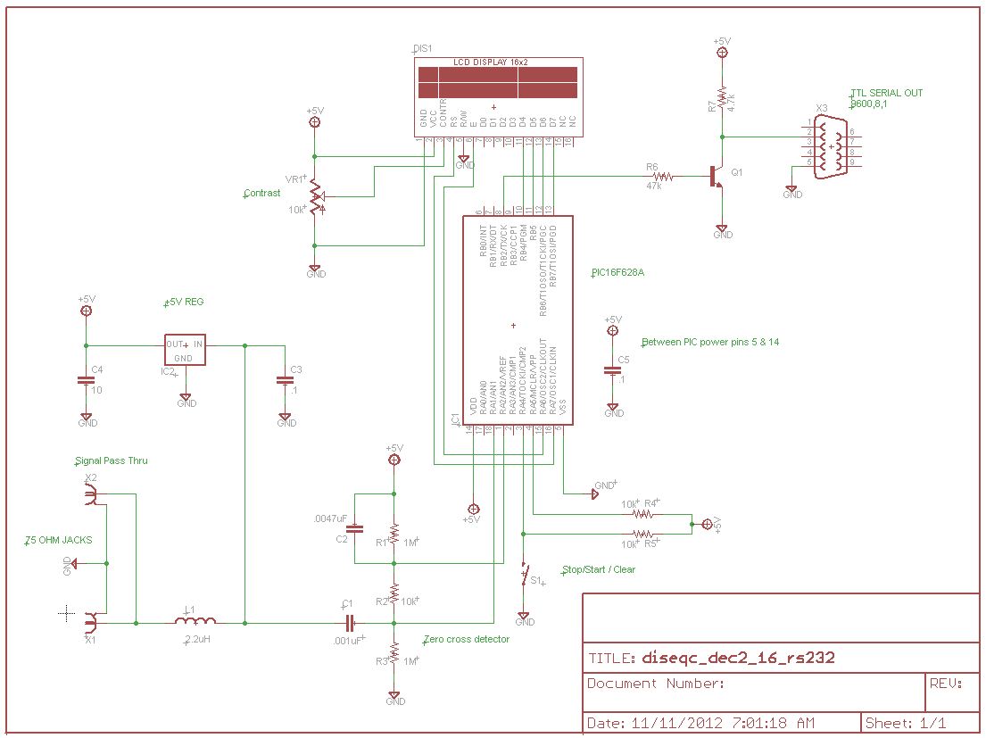
L1 acts like a choke at the IF of the satellite signal, but will pass the much lower freq. of 22k just fine.
I actually have experimented with taking it out, and had it work with not using L1.
I actually have experimented with taking it out, and had it work with not using L1.
Another thing to ponder. I noticed that the units I built from N0QBHs design would not operate behind my microHD. I never pursued that issue.


.
Boards came in from the board house today.
The mess of wires in the background are just temp going from arduino to LCD.
It is working much better on a board like this, with shorter leads on components and no jumper wires everywhere.
I had to modify the timing on the interrupts!
The timing coming out of the Amiko Mini HD SE was almost perfect on the scope coming out of this board!!!
What and how are you doing contrast control on the LCD?
And do you have a serial output for logging?
And do you have a serial output for logging?
External 5k POT, didn't put that in the schematic since, I didn't put the Arduino or Atmel chip and or the LCD, in the schematic.What and how are you doing contrast control on the LCD?
I am using an external SD card module and using the SPI bus.And do you have a serial output for logging?
I need to upload that code at some point, just haven't got it finalized.
Works pretty good though so far. I can pull the chip out and stick it in the computer and look at all the data.
Even have Bluetooth working. Pretty neat to watch it output to my phone.
...but it introduces an error somewhere. After a 5-15 successful decodes I get an erroneous one.
PLEASE LOG IN TO GET RID OF THESE ADS!
- Status
- Please reply by conversation.
Similar threads
- Replies
- 8
- Views
- 700
- Replies
- 11
- Views
- 2K
- Replies
- 1
- Views
- 797
- Replies
- 21
- Views
- 4K