Bad Sensor? Or....?

Status
Please reply by conversation.

RT-Cat

"My person-well trained"
Original poster
May 30, 2011
1,659
236
Cold, Cold,Michigan USA
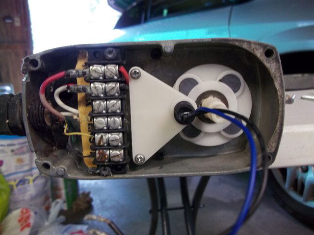
Got the updated PCB back from Titanium Satellite for my ASC-1 very fast. Great service. ASC-1 all back together and hooked up to actuator. Limits set at -5000 and 5000. When attempting to move actuator, it moves less than one rotation and the limit notice shows. Click OK and try the other direction. Same results. So how can you "test" a sensor to see if it is the problem? It is shown in the picture.
ACT T-S.JPG
 
with an ohm meter. Remove the white triangle with the reed switch. disconnect the two wires from the terminal block and connect them to the ohm meter. Now move the reed switch in and out of a magnetic field on watch the ohm meter as the switch should open and close. Probably open normally and closes when a magnet approaches.
 
  • Like
Reactions: Titanium and KE4EST
As the motor energizes and momentarily moves prior to the error message, the power on M1/M2 is present. This narrows the testing to the logic and sensor circuit. The PCB functions were tested after the firmware was updated, so we will initially assume that the PCB is operating correctly.

I would check the ribbon cable connections to the PCB and re-seat the connectors.

Was the voltage selection switch on the AC input accidentally changed from 115Vac to 230Vac?

When the motor is connected to a low voltage source (12v battery), use a multi tester or scope to check for open/close cycles of the reed switch.

Edit: Magic Static has a better testing suggestion posted while I slowly pecked on the keypad... :D
 
Last edited:
Checked the ribbon connectors for the fourth time, checked three times when putting back together, no problem there. Voltage is set 115. Reed switch closes when close to the magnets and opens when away from. This looks where the problem is. When the switch is mounted in position, the switch stays closed. To get it to open I have to move it away from the magnet area at least 1-1/2" On 12 volt battery there are no pulses. Switch stays closed. Is there such a thing as the switch getting super sensitive???
Another question about the magnets. Are they more "powerful" on one side compared to the other? I ask that because they all fell out when I had the unit taken apart. I take it the ASC-1 will not move the actuator unless it is getting a pulse from the sensor....
 
Well, now I'm all magnetized!:bounce Put two "north" across from each other and two "south" in the other holes and the ASC-1 makes that actuator purrrrrrrrr.:clapping
Thanks, MS and Rowdy.
.
To Brian: I like the east/west switch operation where you push and get a "bump" or hold and get constant movement. But when you release, should it run for another 1-1/2 seconds?
.
Ran the power wire through the pipe, the garage attic, the breezeway attic, and 3/4 of the house attic yesterday. That was fun. Now when the sensor wire arrives Friday or Saturday, I get to do that all over again.:(
 
You could bump the opposite direction button for an immediate stop, but personally, I do not like the actuator slamming to a stop... too hard on the mechanicals. For long distance use of the continuous drive, I learn the "feel" of the movement speed and release in advance. The stops and usually within a few counts of the desired position, then use the bump if necessary to single step it in to optimize the Signal Quality reading.
 
  • Like
Reactions: RT-Cat
The seven satellites that I am interested in on my latest 10 foot installation are all set up. I have all the position numbers written down. NOT motor numbers, position numbers. So I am on 127 with the number 15 and move to satellite 101. That position number is 137. Now I move back to satellite 127 and the ASC-1 goes past the signal and stops. I have to bump it back to get signal. Now the position number is different by 8 to 15 counts. If I move to 97 the same thing happens. Goes past and bump back and different position number.
So what is wrong?
 
Is a receiver connected to the ASC1? If so, what receiver? Does the STB have a DiSEqC 1.2 motor assignment number saved for each satellite? Most receivers issue motor and switch commands when a signal is lost. If the DiSEqC 1.2 motor assignment number displayed on the STB is different than the motor assignment number displayed on the ASC1, the STB will instruct the controller to go to the motor assignment number saved in the STB.


I noticed in a different thread that the dish wires were worked on over the weekend. Is it possible that the motor reference was shifted while rewiring? If all positions are off by XX number of counts, likely the actuator/controller need to be resynced.
 
The motor assignment number in the STB and the ASC-1 are the same.
All new setup with the wiring. All new information done.
Position numbers are not "off" by a few counts. Each time I go back to a satellite the numbers are different from the last time the dish was on that satellite. First time on a satellite number may be 110. Next time it may be 118. Next time back there is may be 105. Changes each time and needs to be bumped back to get signal.
 
Referencing the other thread where the counts were correct with the magnets reversed and confirmed after installing new dish wiring, what has changed since those posts?

Maybe a moderator could merge these threads?
When the magnet problem was discovered the actuator was only on a work bench and the ASC-1 was only connected to see if it would work with that old actuator. No settings were done or counts taken at that time. Global reset of ASC-1 was done when it was installed for use. That was just a bench test.
 
Threads Merged....
 
OK, lets start from the top... As the landing count is inconsistent, there is probably lost sensor counts due to a failing reed switch or from motor or grounding/shielding RF noise masking the sensor counts. We need to identify where the problem originates. Since the PCB was tested prior to shipment, I would suggest that we initially proceed on the assumtion that the controller hardware is working correctly.

When reassembling the ASC1, did you make sure that the ground connection from the transformer base was firmly seated to the AC junction/fuse assembly?

Did the actuator and controller work properly together in the past or is this a new install or new components introduced to the system?

Is the dish position count accurate if the controller is out at the dish vs through the wiring into the home?

Does the dish drive long and stop past the target satellite actual position or does the dish stop short before reaching the satellite actual position?

Is the dish connected to a grounded rod?

Is the dish bonded to the home utility ground rod?

How is the actuator power (M1 and M2) wires run to the dish? In a bundle with sensor or a separate wire?

How is the actuator sensor wiring run to the dish? In a bundle with the motor power or a separate wire bundle?

Where is the sensor bundle shield drain wire connected? Controller, actuator, both ends?
I would also agree the PCB is OK.
All connections in the ASC-1 have been quad checked. OK
This is a new install.
Was not tested out at the dish.
It drives long and stops past.
No ground rod. Other bud no ground rod and been working since 1984.
No connection to the utility ground rod. Same as the other working bud.
M1 and M2 are two 14 ga wires. Separate from sensor wires.
Sensor wires not bundled with power wires.
Sensor shield drain connected to actuator ground connection only.
 
Status
Please reply by conversation.
***

Users Who Are Viewing This Thread (Total: 1, Members: 0, Guests: 1)

Who Read This Thread (Total Members: 1)

Latest posts