Birdview parts & accessories

Status
Please reply by conversation.

Anole

SatelliteGuys Master
Original poster
Sep 22, 2005
11,819
14
L.A., Calif.
I've read about 'em, and am currently shopping for a Birdview.
Through many posts on them, I see that some parts may need replacing or remanufacturing.

I've got a buddy with mill and lathe in his garage, and if I needed a new part, I'd have him build it.
Seeing my friends suffer for lack of specialty parts is annoying, and if I can help, I will.
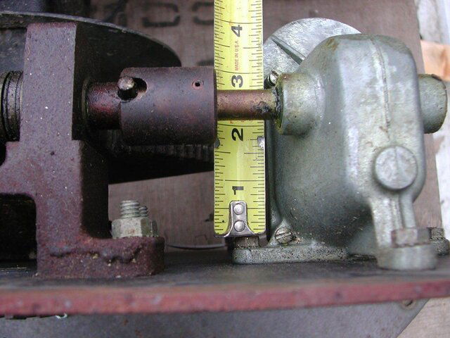
Bronze Bushing:

So far, we've looked at the main bronze bushing.
Without having one here to see, I've had the good fortune to find a photo with dimensions, and run that by my machinist.
It'd be easy to build, and I considered making up half-dozen of them.
But, with the post showing the somewhat similar part from McMaster-Carr, I felt users had a possible source.
That part -might- work, and all it needed was to be cut to length.

Haven't closed the books on that bushing, if someone wants to have more discussion.
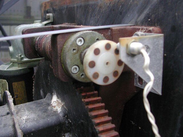
Magnet Wheel:

This is another part I would need, so it makes sense to build up a hand full for other users.
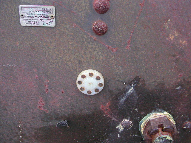
The original kit seems to no longer be available.
Much experimenting has been done here on the forum, so we have plenty of information to make a satisfactory wheel and reed kit.

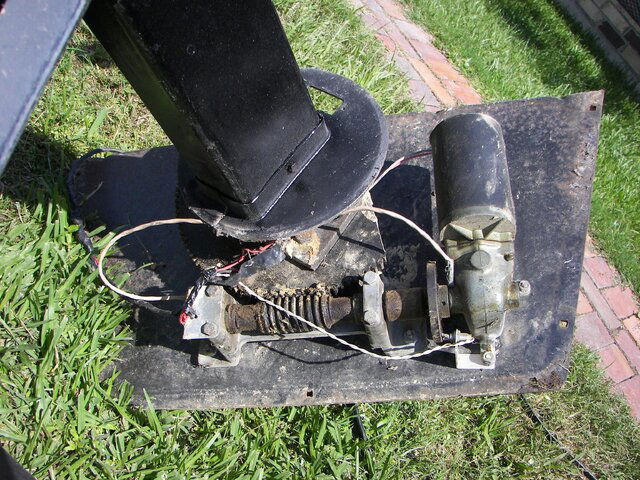
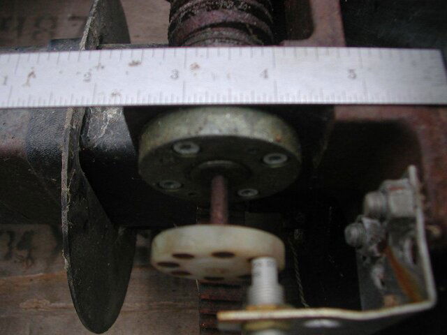
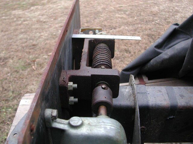
I'm reluctant to make a disc that fits between the motor gearbox and worm gear.
To do so, the coupling needs to be removed by having a pin driven out.
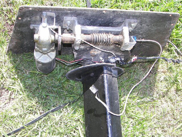
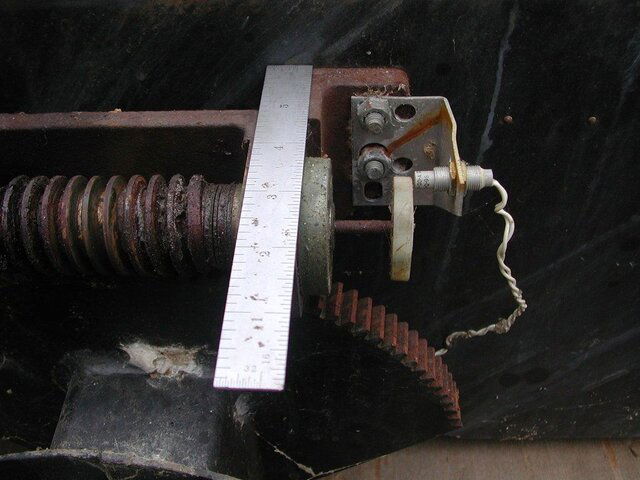
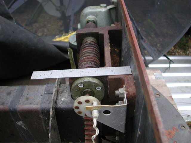
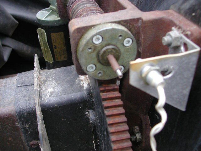
So, my preference is to mount the new wheel at the far end of the worm, where the original gears and potentiometer was located.
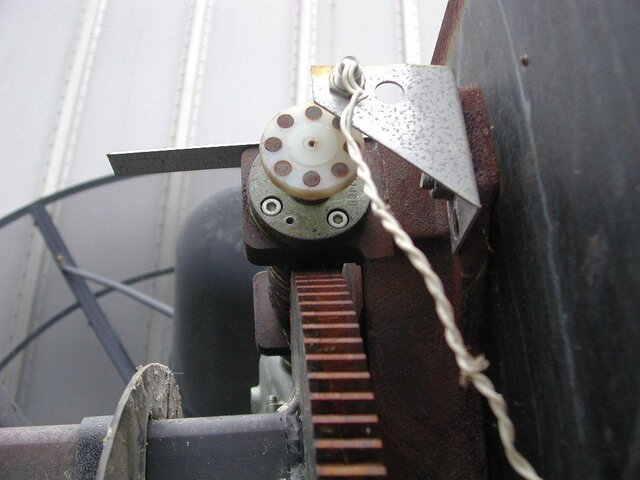
To that end, I'm waiting on Phlatwound to post some pictures of the area, and maybe his original 8-magnet wheel.

If the free end of the worm proves too much trouble, then of course the fall-back position would be between motor gearbox and worm.


So, for now, I'm just waiting for pictures, and of course, more discussion is invited.
And if anyone has a source for the 24-magnet wheel that was used in the commercial kits, please let us know.
 
I'm still not certain how the magnet wheel attaches to the (3/16") shaft. I can see metal with an indentation, when I look into the hole in the center of the magnet wheel, if it has an allen head retainer of some sort it is smaller than the smallest allen wrench I have.

I will experiment with trying to get it off of the shaft, and post my findings in this thread.

Here's some pics of my 8-magnet setup:
 

Attachments

  • Sat Birdview Magnet Wheel.JPG
    Sat Birdview Magnet Wheel.JPG
    113.3 KB · Views: 224
  • Sat Birdview Magnet Wheel2.JPG
    Sat Birdview Magnet Wheel2.JPG
    80 KB · Views: 196
  • Sat Birdview Magnet Wheel3.JPG
    Sat Birdview Magnet Wheel3.JPG
    114.1 KB · Views: 217
  • Sat Birdview Magnet Wheel4.JPG
    Sat Birdview Magnet Wheel4.JPG
    115.5 KB · Views: 199
  • Sat Birdview Magnet Wheel5.JPG
    Sat Birdview Magnet Wheel5.JPG
    106.4 KB · Views: 190
  • Sat Birdview Magnet Wheel6.JPG
    Sat Birdview Magnet Wheel6.JPG
    118.3 KB · Views: 209
The magnet wheel on mine is just pressed onto a 1/16" roll pin....and that roll pin is driven into a hole in the end of the 3/16" shaft.

The 3/16" shaft extends out approximately 13/16", and the roll pin extends approximately 1/4" from the end of the 3/16" shaft. Not sure how deeply the roll pin is inserted into the 3/16" shaft.

4" would be the max diameter of a magnet wheel installed onto the existing 3/16" shaft, larger than that would hit the worm drive gear.

If a larger wheel is desired/required, a slip coupler could be fabricated to extend the shaft, not sure how far you could go and keep it under the plastic cover, but if you moved it an inch out you could probably gain an inch in diameter. You could also increase the shaft diameter with a slip coupler, if desired.
 

Attachments

  • Sat Birdview Magnet Wheel Off.JPG
    Sat Birdview Magnet Wheel Off.JPG
    132.8 KB · Views: 198
  • Sat Birdview Magnet Wheel Shaft.JPG
    Sat Birdview Magnet Wheel Shaft.JPG
    117 KB · Views: 168
So... that 2" diameter, quarter-inch thick round piece of light metal at the end of the worm shaft...
The one with the four screws and extra holes in it....
That is fixed to the worm-support casting, and doesn't turn???
I assumed that it did.

So, basically, the big 1/2" shaft holding the worm is flush with the 2" round disc?
Is its shaft turned down to the smaller diameter?
That's so strange.
And then to have a roll pin in the end of that smaller shaft... that's too weird.

Hopefully, I've missed something.

I'll go look through Linuxman's old posts 'n pix which I believe had the original potentiometer.
Maybe I'll see something there that'll clear this all up.

edit:
okay, I've looked through all my archived Linuxman's Birdview pix.
That 2" x 1/2" metal disc is not shown!
One of his pictures shows a small gear right at the end of the 1/2" worm shaft, and nothing extends beyond.
Another picture by BrownCow shows the little gear right on the end of the 1/2" shaft, too.
Nothing extends outward.

So, that makes me ask... is the 8-magnet conversion a factory mod?
How can it be done in the field?

I'm beginning to like the place Linuxman put his magnet wheel, more and more.
That's between the motor/gearbox, and the coupler to the worm shaft. :(
 
Last edited:
The dish that Phlatwound now has was modified in the field by the installer who gave me the address of where it was located.

That's how I acquired that particular dish, and that was the installer's purpose in going out to the home was to upgrade the Birdview from the potentiometer to the magnet wheel.

I have two spare shafts here given to me by a member of this forum when I got my first Birdview, and Phlatwound is correct. It is simply a rolled pin driven into the end of the worm-gear shaft. I would take close up pictures buy my family took the camera out of town. They will be back later tonight and maybe I can get some pics then or tomorrow morning.

To implement the magnet wheel on the end would require drilling and tapping the hole on the end of the shaft for stability. If you have to go to that extent, the wheel between the motor and the coupler is the way to go. Less work and complications.

BTW, I think it is a wonderful idea to build some of these parts and make them available. I'll buy at least one of each just for spares. :)
 
So... that 2" diameter, quarter-inch thick round piece of light metal at the end of the worm shaft...
The one with the four screws and extra holes in it....
That is fixed to the worm-support casting, and doesn't turn???
I assumed that it did.

Correct, it does not turn.

So, basically, the big 1/2" shaft holding the worm is flush with the 2" round disc?
Is its shaft turned down to the smaller diameter?
That's so strange.
And then to have a roll pin in the end of that smaller shaft... that's too weird.

Hopefully, I've missed something.

Actually the big shaft is 3/4", the shaft coming out of the gearbox on the motor is 1/2", the size changes at the coupler. and yes, it is basically flush with the disc, protrudes about 1/16".

And it's even weirder than you thought........the "3/16" shaft" that the small roll pin is driven into.....is actually another (3/16") ROLL PIN! :eek: It was turned all the way "down" and I didn't notice it before.

The larger roll pin is driven into a hole in the end of the 3/4" shaft, pretty crude setup.

So, that makes me ask... is the 8-magnet conversion a factory mod?
How can it be done in the field?

Explained above.

I'm beginning to like the place Linuxman put his magnet wheel, more and more.
That's between the motor/gearbox, and the coupler to the worm shaft. :(

That may indeed be the way to go. Im going to pull that large roll pin out and see if there are any threads tapped into the end of the 3/4" shaft. If so, good, that may be a good way to attach something to that end, to allow a wheel to be mounted out there. :)

Edit: I see linuxman confirmed what I thought I saw here, good deal.
I just put the one I have without the roll pin and there are no threads in it. Just tapered and then a smooth hole.
 
Thanks for the input, guys. - :up

So, if all the worm-shafts in the field have a hole in the end, which can take a roll pin, that's interesting.
I'll run it by my machinist.
But, how was the original plastic gear held to the end of the (now: ) 3/4" worm shaft?

I don't want a Mickey Mouse design that is either difficult to install, nor wobbly.
If we have to go to the 1/2" motor shaft, so be it. - :cool:
I know exactly how much trouble putting the wheel there would be, and it's not zero. - :eek:
So pardon me for harping on the pot-location, but since I don't have one of the assemblies here in my hands, the answers aren't 100% obvious.
 
progress on replacement parts

I did some brainstorming with both guys today.
Guess I've given up and am focusing on locating the wheel between the motor's gearbox, and the 1/2" to 3/4" coupling.

Got to come up with three parts for the magnet conversion kit:

- the wheel with magnets, setscrews, et al.
That has been pretty well hashed out.
Ordering some test magnets and other raw material , soon.

- the reed assembly
May be adjustable to/from the magnets for fine tuning
That may have a threaded body or . . . (we're still talking 'n testing)

- a bracket to hold the reed
Would like to use an existing nut or bolt
Suggestions are welcome - even to replacing an existing motor screw with a longer one
May have to make a paper cutout of how to drill and fold the bracket.
Want it to be a real custom drop-in-and-it-fits sort of thing.


I'll also look locally for the bronze bushing.
If I find any, I'll trim one to size and find a guinea pig to test drive it. ;)


While looking through the extensive Birdview photo gallery over at my buddy's house tonight, we discovered another wear part.
That 1/2" to 3/4" coupling is beaten up pretty bad on some dishes.
I'll look for the part somewhere, and make sure it's available.
Replacing it will reduce slop and allow for more accurate positioning.


Any questions or advice is welcome. - :up
 
Not trying to re-re-reinvent the "wheel" here, but was it discussed to tap the hole in the end of the 3/4" shaft to accept a small threaded shaft, on which the new and improved magnet wheel could be placed?

Linuxman has already proven that going onto the 1/2" shaft can work very well, I'm just throwing a thought out there.

Also, re:1/2"-3/4" coupler....is there any reason why that connection needs any "slop", or shock-absorbing properties, whatsoever?

If not, there are a lot of ways to make that connection solid (thru-bolt or drill/tap in some allen set screws).

If a little shock absorption is desired, that could be done also.

I'd be glad to guinea pig a bushing, it's easy since my mount off the pole and no dish is attached......but that uninstalled status is going to change one of these days! :)
 
Not trying to re-re-reinvent the "wheel" here, but was it discussed to tap the hole in the end of the 3/4" shaft to accept a small threaded shaft, on which the new and improved magnet wheel could be placed?
I want to use the clean end of the worm shaft so bad I can taste it.
So, when I say I've given up on it, it's because I've seen too much variability in the pictures I've examined.
A company-man, sent to "fix" a user's dish could replace anything he may need to, to get it working again.
You, as one user, cannot swap out major components just 'cause it's convenient.
So, we pretty much have to live with whatever worm shaft you have.
Having the user tap it in the field is not something I would expect a user to do. :eek:
Linuxman has already proven that going onto the 1/2" shaft can work very well, I'm just throwing a thought out there.
Well, it's also where the commercial third-party kit mounted.
Maybe they knew something we're just discovering. :cool:
Also, re:1/2"-3/4" coupler....is there any reason why that connection needs any "slop", or shock-absorbing properties, whatsoever?

If not, there are a lot of ways to make that connection solid (thru-bolt or drill/tap in some allen set screws).

If a little shock absorption is desired, that could be done also.
I discovered the extra wear/slop in one of the pictures during a slide show with my main machinist last night.
I'll post it below, and you can see what got me so upset.
Not just a little slop, but some serious wear to the part! - :eek:
I'd be glad to guinea pig a bushing, it's easy since my mount off the pole and no dish is attached......but that uninstalled status is going to change one of these days! :)
In your place, I can understand the urge to get 'er done.
I don't think I'll be able to get everything ready for you to test in a short enough time frame, especially with the holidays.
However, we'll make the best of it. - :up

Last minute addition. I think I have the definitive picture of where that bronze sleeve is mounted.
Cutting down the commercial one would just have a somewhat smaller diameter lip under the nut (see attached picture).
That's probably not going to be any trouble.
See picture below (I think it's from Swampman).

Also, I'm going to see if I can get the pre-made part locally.
If you (or anyone) could get me a picture of the far end (non-lip) of that bushing, I'd appreciate it.
Is the length critical, at all?
AND, what is at the other end of that shaft? Another such bushing?
I probably already have pictures somewhere, but just don't know what to look at.
 

Attachments

  • Sat Birdview Shaft Clearance2.JPG
    Sat Birdview Shaft Clearance2.JPG
    117.2 KB · Views: 240
  • DSC07478.JPG
    DSC07478.JPG
    224.8 KB · Views: 189
I want to use the clean end of the worm shaft so bad I can taste it.

Me too!

Well, it's also where the commercial third-party kit mounted.

Do you have a pic of that setup?

I'll post it below, and you can see what got me so upset.
Not just a little slop, but some serious wear to the part! - :eek:

I will look at that again today, that may not be wear, believe it may have been made with that much slop, from the factory.

Cutting down the commercial one would just have a somewhat smaller diameter lip under the nut (see attached picture).
That's probably not going to be any trouble.

Smaller shoulder (lip) should not be a problem.

If you (or anyone) could get me a picture of the far end (non-lip) of that bushing, I'd appreciate it.

Do you mean you'd like a pic of the (far end of the) bushing? Or where that end of the bushing ends up at?


Is the length critical, at all?

Not sure, it may bottom out on something, I'll look.

AND, what is at the other end of that shaft? Another such bushing?

Do you mean on the bottom section of the mount? Maybe this post/thread will help?

http://www.satelliteguys.us/c-band-...8-birdview-mount-lubrication.html#post1452730
 
There is serious slop in the coupler. I solved by drilling the hole out bigger and put a bolt through with a locking nut.

I see no reason for that much slop unless it gives a little jump start for the motor when reversing movement. It has to be taken out if you are serious about where the dish lands for Ku signal. we're talking 3 or 4 pulses of slop. :yikes:

I wrote about it and posted pictures in my original Birdview thread where Caddata was so much help to me. (Which I will be eternally grateful for!)

Speaking of motors! I have a call in to Von Weise which is now part of White and Green Motors and no long affiliated with Fasco.

Hopefully the guy will get back to me today about new motor availability and re-building costs etc.

Anole and I talked Saturday about getting them re-built, so we will find out what the manufacturer charges. :)
 
This may be another way for you guys that want to increase the counts on a birdview drive to think about, an this is what I am going to do when I get some time to do a birdview mount. why don't you just try to run the magnet wheel faster with a gear reduction like the orginal Birdview came with a 10k pot. the small gear driving off the worm an a larger 2nd gear with a magnet wheel glued to it. in other words get a idler gear with a magnet wheel atached to it some how.

Now I just finished up a mount that I have been working on for a wile, an on this mount running from the worm it had a small plastic gear running 2 larger gears, driving a 10k pot. now from age all the gears where in bad shape, cracked an missing teeth, so dicarded all, an use 2 gears from a old actuator, larger gear comming off the worm an smaller gear running from the big gear, which gave me a 2.7 to 1 turn of the worm drive. now i screwed a magnet wheel (4" home made with 22 magnets) to that gear an it increased counts by a great deal. may be to much, cause i used a powertech G-bow to test it out, an have over 4100 counts from limit to limit, but the arc for that dish will stop about Telstar-12 so can't run a full arc with its pole location.

what I need to do is get a camera an try to post some pictures, because a picture is better than words. an beleive me it was easy to do, I have got lots of old actuators kicking around, an scrounging parts was easy, its the time factor that I have a problem with.
 
.....what I need to do is get a camera an try to post some pictures, because a picture is better than words. an beleive me it was easy to do, I have got lots of old actuators kicking around, an scrounging parts was easy, its the time factor that I have a problem with.

That sounds very interesting, please post some pics if you can. :)
 
after market 24 magnet mod

Well, it's also where the commercial third-party kit mounted.
Do you have a pic of that setup?
Here is a picture, I think provided by SwampMan.
It appears to be the same 24-magnet mod that Linuxman used on his first Birdview.
Of course, this one has been in the field for a while. - :rolleyes:
Just zoom in for a good close view.
 

Attachments

  • 100_0325.jpg
    100_0325.jpg
    1.6 MB · Views: 202
  • 100_0329.jpg
    100_0329.jpg
    1.7 MB · Views: 219
Here is a picture, I think provided by SwampMan.
It appears to be the same 24-magnet mod that Linuxman used on his first Birdview.
Of course, this one has been in the field for a while. - :rolleyes:
Just zoom in for a good close view.

Yes, that is the same commercial magnet wheel I have that I bought from Skyvision for my first Birdview.

Stogie now has it. :)

Stogie has to be one of the luckiest guys I know. His dish has the commercial magnet wheel already installed, and the commercial scaler conversion already installed.

All he had to do was set it in concrete and tune it in. :eek:
 
Here is a picture, I think provided by SwampMan.
It appears to be the same 24-magnet mod that Linuxman used on his first Birdview.
Of course, this one has been in the field for a while. - :rolleyes:
Just zoom in for a good close view.

Thanks, I hadn't seen those pics before.

Is the contraption/wire coming off the end of the 3/4" shaft part of the old potentiometer-style setup? :confused:
 
......Stogie has to be one of the luckiest guys I know. His dish has the commercial magnet wheel already installed, and the commercial scaler conversion already installed.

All he had to do was set it in concrete and tune it in. :eek:

Well, where's the fun in that?

That almost sounds like cheating! ;)
 
Status
Please reply by conversation.
***

Users Who Are Viewing This Thread (Total: 1, Members: 0, Guests: 1)

Who Read This Thread (Total Members: 1)