So sometime a couple of years ago I was just browsing electronic parts like I tend to do and reading around. I came across a AD9850 DDS Module on eBay for around $8.

I researched a little and saw where people where making homemade VFO's with them, using Atmel and PIC chips or Arduino boards, Parallax, etc micro-controllers. I thought hey I could make a signal generator or something with this board. I ordered it, it came in, and I stuck it in a drawer, with other misc. items I impulse buy on eBay.
Some time early last winter, I came across it in the drawer and decided to research a little more and see how hard it would be to at least hook this up and make it do something. Actually I found a project using an Arduino Uno. I downloaded it, and modified the code to work with an Arduino Due(because that is what I had on the bench at the time). I hooked up a TFT display and rotary encoder and ta da, I could tune 1Hz to 30MHz and a little past and get an output. Although it got pretty low after 25MHz it was still outputting. Nothing a buffer amp would not fix if I decided to go further.
An interjection is necessary here. I have read several of Jack Purdums books on programming in C. A few years ago I didn't even realize he was a ham. Recently he wrote a book about Arduino and ham radio projects and a light went off in my head. I am also a member of some Yahoo! Groups dealing with ham radio related stuff. Wait a minute, Jack W8TEE is the author of the books I have read in the past.
Okay, back to it. Anyway he is working on a Antenna Analyzer project, that will be coming out in a future issue of QST. He gave some of us in the group a link to some of his progress, so from there I got really interested in doing something more with this DDS module.
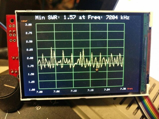
I started gathering all the parts to go from his schematic and parts list. Then a few weeks ago Brian Gohl, AI6US aka Titanium on here, was talking about Antenna Analyzers with me. I told him you know what I will just build my own. In fact I have built two of them now and they are working very well.
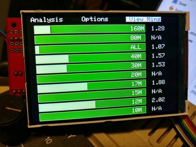
Now mind you I want to give all the credit to Jack Purdum, W8TEE and Farrukh Zia, K2ZIA, I just took their rough draft write up and put it all together. I have since went in and made changes to the code to suit me like colors and looks and such on the screen. Add a couple of screens and things like that...I have not modified the core functions/methods that do all the heavy lifting and it works great.
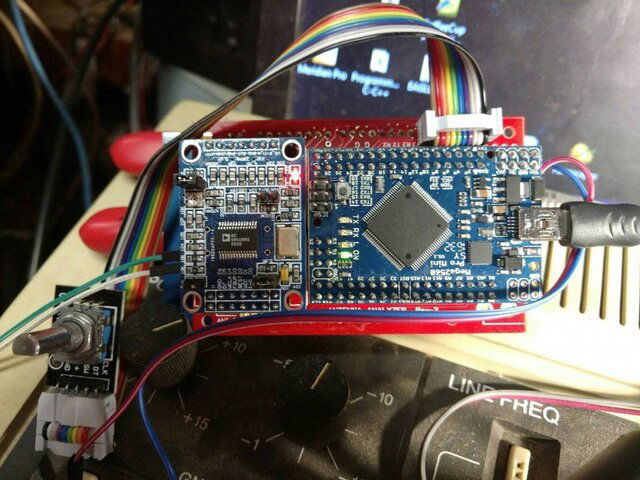
It all runs on an Arduino Pro Mini (Mega Version) you will see in the picture below beside the AD9850 Type II.
I got permission from Jack before I made this post and his only request was that I not post any of the particulars and source code until the final is ready and it is in QST. So stay tuned to QST and you will see this again soon!


You will see the DDS Module on the left and the pro mini on the right.
Below you will see it is all operated with a single rotary encoder for the time being. Just turn the knob to select what you want from a menu and push the built in button to select.
I just got to get this thing cased up with a power switch, battery holder, SO-239, etc.
I researched a little and saw where people where making homemade VFO's with them, using Atmel and PIC chips or Arduino boards, Parallax, etc micro-controllers. I thought hey I could make a signal generator or something with this board. I ordered it, it came in, and I stuck it in a drawer, with other misc. items I impulse buy on eBay.
Some time early last winter, I came across it in the drawer and decided to research a little more and see how hard it would be to at least hook this up and make it do something. Actually I found a project using an Arduino Uno. I downloaded it, and modified the code to work with an Arduino Due(because that is what I had on the bench at the time). I hooked up a TFT display and rotary encoder and ta da, I could tune 1Hz to 30MHz and a little past and get an output. Although it got pretty low after 25MHz it was still outputting. Nothing a buffer amp would not fix if I decided to go further.
An interjection is necessary here. I have read several of Jack Purdums books on programming in C. A few years ago I didn't even realize he was a ham. Recently he wrote a book about Arduino and ham radio projects and a light went off in my head. I am also a member of some Yahoo! Groups dealing with ham radio related stuff. Wait a minute, Jack W8TEE is the author of the books I have read in the past.
Okay, back to it. Anyway he is working on a Antenna Analyzer project, that will be coming out in a future issue of QST. He gave some of us in the group a link to some of his progress, so from there I got really interested in doing something more with this DDS module.
I started gathering all the parts to go from his schematic and parts list. Then a few weeks ago Brian Gohl, AI6US aka Titanium on here, was talking about Antenna Analyzers with me. I told him you know what I will just build my own. In fact I have built two of them now and they are working very well.
Now mind you I want to give all the credit to Jack Purdum, W8TEE and Farrukh Zia, K2ZIA, I just took their rough draft write up and put it all together. I have since went in and made changes to the code to suit me like colors and looks and such on the screen. Add a couple of screens and things like that...I have not modified the core functions/methods that do all the heavy lifting and it works great.
It all runs on an Arduino Pro Mini (Mega Version) you will see in the picture below beside the AD9850 Type II.
I got permission from Jack before I made this post and his only request was that I not post any of the particulars and source code until the final is ready and it is in QST. So stay tuned to QST and you will see this again soon!


You will see the DDS Module on the left and the pro mini on the right.
Below you will see it is all operated with a single rotary encoder for the time being. Just turn the knob to select what you want from a menu and push the built in button to select.
I just got to get this thing cased up with a power switch, battery holder, SO-239, etc.


 to Satelliteguys CoraDias!