gbox/vbox power booster

  • WELCOME TO THE NEW SERVER!

    If you are seeing this you are on our new server WELCOME HOME!

    While the new server is online Scott is still working on the backend including the cachine. But the site is usable while the work is being completes!

    Thank you for your patience and again WELCOME HOME!

    CLICK THE X IN THE TOP RIGHT CORNER OF THE BOX TO DISMISS THIS MESSAGE
Status
Please reply by conversation.

ynnedibanez

SatelliteGuys Pro
Original poster
Dec 7, 2009
536
58
Greeneville, Tennessee
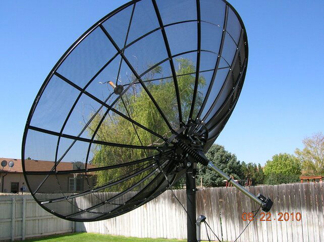
i was looking at the specs on my vbox and noticed it had a max current rating of 2.2 amps, and my von weise actuator has a max current draw of 2.75 amps.....
my first thought was D*mn!TTTTTT!!!!!!!!!!!
i am sure that that would be hard on the small transformer in the vbox, and probably eventually burn it up.
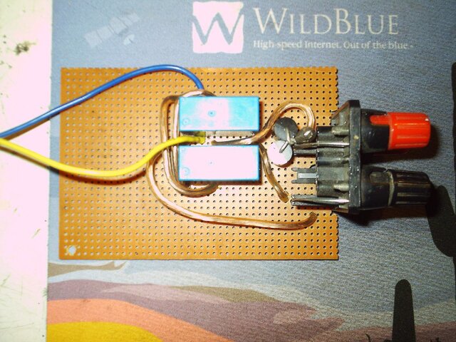
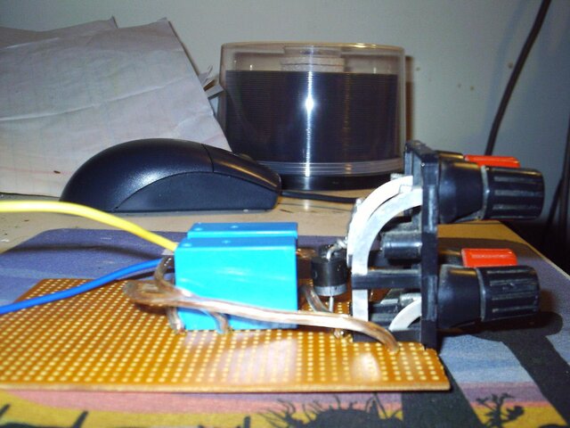
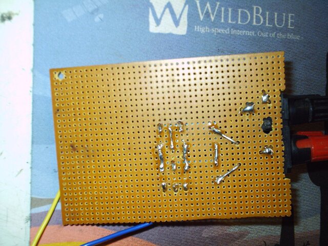
so i designed a fairly simple circuit to take the strain off of the vbox:D
if you don't have experience in electrical circuits, and if you don't understand this circuit fully, DON'T TRY BUILDING IT!!!!!
THIS CIRCUIT DOES USE LETHAL VOLTAGE!!!
IF YOU DO SOMETHING WRONG, YOU COULD BE KILLED OR FRY EXPENSIVE EQUIPMENT.
TRY IT AT YOUR OWN RISK!!!!!
(sorry about the caps)
anyway, with the disclaimer out of the way, heres the schematic.
hope this helps some of you with h-h motors and actuators that draw lots of current.
Denny
 

Attachments

  • vbox power booster.bmp
    2.7 KB · Views: 429
Last edited:
Is your max current draw of 2.75 amps measured or specs? I have a 12 foot mesh with a 36 inch actuator that I measured the current draw. When pushing the dish uphill from 135W to 87W, I start out at 1.4 amp, 25 volts. As it gets closer to 87W, it only draws .6 amp at 27 volts.

I agree those units may be under-powered. I fried my GBox V3000 while moving my dish. It was fairly new but I don't really like the wait or possible hassle of returning something so I tore into it myself. I found a diode in the diode bridge for the actuator power had overheated (scorched marks on the board, bubbling under the foil) and shorted out. That caused the transformer to overheat and open the primary. Unfortunately, this unit doesn't have a fuse.

The transformer rating (from a tag on the part) is 32v ac 1300ma, 12v ac 250 ma. The diodes were PL207's which doesn't cross in any reference book I have but it looks like a 2 or 3 amp size. Fortunately, I have a sizeable junk pile and found suitable (and larger) replacements. And I also installed a fuse in the circuit. All is well now. Good luck.

its from the specs
judging by the voltage drop when yours is under heavy load, (from 32v at no load, to 25v at heavy load) i would assume that it is pushing the transformer fairly hard at 35w even though the max output on the 32v windings is rated at 41.6w
guessing, i would say that 41.6w is instantaneous peak with continuous safe current draw being a bit less
also, hearing about your diode frying makes me want even more to take the strain off the vbox
it seems like it is made for less current draw than some of the more power hungry dish movers can use in certain circumstances (maybe high winds, or snow on the dish)
i took my vbox apart, it also has no fuse, i think that will be the only internal mod i make to the vbox.
the transformer and diodes do seem quite small to drive a motor as large as the one on the von weise actuator, also, i noticed that there is no capacitor on the power supply that runs the motor, it would seem that when the motor first starts that that would cause lots of unnecessary strain on the power supply.
also there were a few bad solder joints.
i also figure that if i build a strong enough power supply to avoid the voltage drop it would move the dish faster.
tonight i started digging through my junk boxes to find parts to build this thing.
i'll let you know how it goes, and thanks for the input:),
Denny
 
well, i have finished the relay circuit.
attached are some pix.
also, i am thinking of adding a button that will temporarily boost the voltage by selecting another winding on the transformer so if i have to move a long ways across the arc it will do it faster.
does anyone know how durable these von weise motors are?
will they handle 45-50v for a short period of time?
thanks,
Denny
 

Attachments

  • top booster.JPG
    top booster.JPG
    323.8 KB · Views: 264
  • side booster.JPG
    side booster.JPG
    210.3 KB · Views: 251
  • bottom booster.JPG
    bottom booster.JPG
    289.7 KB · Views: 245
1st off nice relay circuit, an simple.

an as far as the extra voltage, I would bench test it with a hand on the motor to see just hot hot that it may get with 50 volts verse 36, it may be ok.

the amp draw of a actuator or a horizon motor mount is some thing that should be checked from time to time an it would stop a lot of problems that people have, an even more so when dealing with used motors an dishes. an their are several factors that will cause a high amp draw of a motor.

even that a motor has a amp draw on it, it does not mean that is what they will run at. the amp draw listed are their on their motors is a max amp draw before problem will arise, either with it's power source or the motor it's self.

now here I use several horizon mounts that I will fit other types of dishes on them. I just finished up a 1.8meter Channel Master on a H-mount an from a vertical position of the dish it has a 1.1 amp draw, wile spiking at 1.68 on start up, but if it's in the middle of the ark an moves down the amp draw is a lot less .7. now I even have a 10-foot ChannelView dish an it is very heavy in the 400 to 500 lbs range, an it also has a real low amp draw with a 167 gear ratio an well under 1 amp draw, an only will spike to 1.1 on start up, but when I tested it with a 37 to 1 motor the amp draw was well over 2-amp an spike of 3.7 on start up, an this von weise motor has a 2.7 amp draw.

here are some picture of my meter wile testing the ChannelView's amp draw.
1st picture is A/D of dish moving down.
2nd picture is A/D of dish moving up from a vertical position.
 

Attachments

  • 100_0101.JPG
    100_0101.JPG
    890 KB · Views: 187
  • 100_0103.JPG
    100_0103.JPG
    557 KB · Views: 174
1st off nice relay circuit, an simple.

an as far as the extra voltage, I would bench test it with a hand on the motor to see just hot hot that it may get with 50 volts verse 36, it may be ok.
thanks :)
results of the bench, err, living room floor test below;)
well, at no load, with a von weise v76-5 sitting in the living room floor, i ran 45v into it with a 61,000 mfd capacitor strait from the power supply until it was fully extended, and then reversed polarity and retracted it. i repeated this several times. it was about 20 seconds faster per cycle than at 36 volts without a capacitor.
it handled the extra voltage quite easily, so i increased the voltage to 80v without a capacitor (for lack of a large one that would handle that voltage on hand) and after extending and retracting it a few times the motor did get just a little warm to the touch, but man, it was FAST!!!!
with a heavier load at this voltage i suspect that the motor would draw enough current to burn itself up quickly, but right now, i have no load, so for kicks i tested it further
at all 3 voltages, it drew relatively close to 1/2 amp with 36v being a little below a half amp and 80 being a little above a half amp, but i am sure that with a load, this would change drastically
i then tried the circuit with the v-box6, and at 80v, the sensor sent pulses to fast for the v-box to interpret them, plus, i noticed at 80v, when i killed the power, the inertia kept the actuator moving for just a split second, but long enough to pass a couple more magnets under the sensor, so i would assume as speed goes up, accuracy goes down.
with 45v on the relay circuit, the v-box performed flawlessly, but i am not sure about the accuracy it would have at that speed.
i wish i could put up a bud here so i could test that :(
 
Vbox6 transformer

I too have a Vbox6 (DMS) positioner which I believe has a bad transformer. There is no tag on mine for details. Can I assume the output should be 36VAV and 12VAC on either the blue or yellow wires. The blue wires go to the small diodes and the yellow wires go to the big diodes - there fore blue should be 12VAC and yellow 36VAC.None of the LED's light up and I see no bulging capacitors or fried components. I was using it to control a 12' BUD - so maybe I overloaded it. Where did you get your higher amperage transformer?? I think 36VAC is a doorbell transformer - maybe 12VAC could be a "wall wart" power supply. Later today I will get my multimeter out and do some testing. Any help appreciated........thank you - Mongo1
 
It's interesting that some people have no problem moving a 12 footer with a Gbox or Vbox while others do. I wonder why no one sells a Vbox or Gbox that can handle the current draw for a 12 footer. I've seen some Vbox 6000's that are rated for 12 footers but they're run off of 230VAC and the specs say they put out only 1.8A. Anyway, we shouldn't have to modify stuff to make it work.
 
johnnynobody said:
It's interesting that some people have no problem moving a 12 footer with a Gbox or Vbox while others do.

Some dishes by design are well balanced and do not require much effort to move, other dishes can barely be lifted off the ends of the arc. This is another reason that I would use the longest throw actuator arm possible and relocate the actuator arm connect point as far away from the pivot as possible. This also adds extra motor revolutions and pulse counts to the ends of the arc for better aiming resolution.
 
no kidding!

This is another reason that I would use the longest throw actuator arm possible and relocate the actuator arm connect point as far away from the pivot as possible.
This also adds extra motor revolutions and pulse counts to the ends of the arc for better aiming resolution.
After saying this a few times, and getting blank stares, I've given up beating the drum.
It's all good: more counts, better leverage, lower current...

Some dishes by design are well balanced and do not require much effort to move, other dishes can barely be lifted off the ends of the arc.
This on the other hand, is a whole different kettle of fish.
Other than adding counter weights (which 99% of dishes don't have), what could you do?
I suppose some mount geometry may be more conducive to the solution, but I confess I've never seen an obvious example.
 
This on the other hand, is a whole different kettle of fish.
Other than adding counter weights (which 99% of dishes don't have), what could you do?
I suppose some mount geometry may be more conducive to the solution, but I confess I've never seen an obvious example.

"This is the other hand"
I have made from scratch polar mounts, and fitted on to reflectors that where designed for AZ/EL, as well as fitting horizon mounts onto other dishes than for what they where not design for. and have done this a lot in the past 25 years dealing with satellite dishes of all types.

also like Brian said, some dishes are well balanced, wile others are not, and this is so true when you are dealing with certain dish manufactures. now some times you can improve with the actuator mounting points, by extending them and or from my dealings if you can move the actuator closer to center of the mount it will take less effort to push a dish up, but when you are dealing with a very heavy dish this will become more of a challenge than you think it could be. what I do when I am planning for a actuator locations on a mount that I am building I will put a big bolt in place where the actuator will mount, then I use a inch pound wrench to see just how much force it takes, before all is final welded in place, and some times this will be changed several times before you find the best location, with less force.

now you all need to take this into consideration too, most people here are dealing with older dishes, and actuators, which can have worn pivot points then it will create some resistance, older motors always will have a higher amp draw than a newer motor will. also some people will not use the correct wire going to a motor also which again will add more resistance into the mix. now all of these needs to be taken into consideration when checking the amp draw of you're motor driving a dish either big or small.

what can and will help people with big heavy dishes is actuator that has a lower gear ratio, you're dish will move slower, and will have less strain on its power source. but their is not any more manufactures left that you can purchase different gear ratios that I know of to this day.
 
Some dishes by design are well balanced and do not require much effort to move, other dishes can barely be lifted off the ends of the arc. This is another reason that I would use the longest throw actuator arm possible and relocate the actuator arm connect point as far away from the pivot as possible. This also adds extra motor revolutions and pulse counts to the ends of the arc for better aiming resolution.

From looking at my KTI, attaching the actuator arm to the ribs to mount it away from the pivot point isn't possible. Doing this on a Paraclipse wouldn't be a problem though.
 
36v transformer

I too have a Vbox6 (DMS) positioner which I believe has a bad transformer. There is no tag on mine for details. Can I assume the output should be 36VAV and 12VAC on either the blue or yellow wires. The blue wires go to the small diodes and the yellow wires go to the big diodes - there fore blue should be 12VAC and yellow 36VAC.None of the LED's light up and I see no bulging capacitors or fried components. I was using it to control a 12' BUD - so maybe I overloaded it. Where did you get your higher amperage transformer?? I think 36VAC is a doorbell transformer - maybe 12VAC could be a "wall wart" power supply. Later today I will get my multimeter out and do some testing. Any help appreciated........thank you - Mongo1

The 36v transformer out of an old analog receiver that had dish positioning would work in a modern V or G box. People still have these in closets or basements and can be had for the asking. Anywhere you see an old C-band dish just knock on the door.

Alternately you can get one from a electronic surplus store. Here is a listing at Fair Radio Supply.

701-121 - 36VCT 3A Secondary. 115VAC 60Hz Primary. 3.3x3.3x2.8, End Bell style, 6 lbs sh.
$8.00 each

https://www.fairradio.com/catalog.php?mode=view&categoryid=1546

Jim
 
johnnynobody said:
From looking at my KTI, attaching the actuator arm to the ribs to mount it away from the pivot point isn't possible. Doing this on a Paraclipse wouldn't be a problem though.

Why isn't it possible? Attach a photo of the back of the KTI and you mounting point.

Simply fashion a mounting point to the rib that allows the actuator arm to connect further out towards the reflector edge. The mounting point might need to be fashioned so the actuator arm clears the curvature. I have fabricated a simple 12" triangle to attach to the ribs beyond the manufacturer's mounting point to allow a longer jack to clear the curvature.
 
Anole said:
Other than adding counter weights (which 99% of dishes don't have), what could you do?
Add a counter weight on a cable that contacts the ground as the dish reaches the neutral balance point.... Had to do this once on a 18' monster!
 
Why isn't it possible? Attach a photo of the back of the KTI and you mounting point.

Simply fashion a mounting point to the rib that allows the actuator arm to connect further out towards the reflector edge. The mounting point might need to be fashioned so the actuator arm clears the curvature. I have fabricated a simple 12" triangle to attach to the ribs beyond the manufacturer's mounting point to allow a longer jack to clear the curvature.

It's possible but I don't think it'll be a good idea to attach anything to these aluminum ribs because they're easily damaged.
 

Attachments

  • DSCN1101.JPG
    DSCN1101.JPG
    767.4 KB · Views: 165
what goes around . . .

January 2008 discussion of extending the actuator to get more counts.
Thanks to Brian for bringing it up again.
Maybe more users will actually -do- it! - :rolleyes:

There have also been previous discussions of counterweights.
In some cases, to make SG2100 motors better handle a big dish.
We need to dredge up some of these ideas and talk about 'em again. - :up

Thanks for the link. However, we probably should start another thread on this even though it's somewhat related. I might be able to get a higher pulse count by adding a long bar to the back of the mount ring since there are 2 holes on the ring that I could attach the bar to for support. Another option is to drill a hole(s) into the appropriate rib to attach the actuator arm to. But, as I've mentioned, the ribs on the KTI are made of very lightweight aluminum (that's what you get on a new $2000 antenna these days). I guess I should've tried to repair the Paraclipse (but since insurance paid for a new antenna.....).

I suppose that modifying a Vbox or Gbox to use a higher current transformer and diodes would be a good idea if there isn't anything else available and economical. The only "problem" is that you'll void the warranty.
 
Adding to the mix:

Find an old GI 2400 or similar that had an outboard actuator drive box. In the case of the 2400, the actuator drive is controlled through a DIN connector. Shorting the appropriate pins drives the dish in the appropriate direction. The polarity sensing relay circuit the the OP designed could easily be adapted to control one of those boxes. Better than building your own 36V drive circuit in that it's all like UL approved and fused and all the rest of that stuff that will avoid those nasty fires and electrocutions <g>.
 
johnnynobody said:
It's possible but I don't think it'll be a good idea to attach anything to these aluminum ribs because they're easily damaged.

If the ribs are too light weight, attach an angle iron arm to the ring and move the attachment point out one, two or more feet... The jack appears to be able to support at least a few additional feet of offset. You wouldn't believe the difference this modification will make in increasing the aiming accuracy and lifting capacity. I would guess that your motor would start reliably landing on the satellites!
 
Status
Please reply by conversation.

Users Who Are Viewing This Thread (Total: 0, Members: 0, Guests: 0)

Who Read This Thread (Total Members: 1)