gbox/vbox power booster

Status
Please reply by conversation.
Does anyone have schematics for the Gbox and Vbox?
 
It's possible but I don't think it'll be a good idea to attach anything to these aluminum ribs because they're easily damaged.

More photos of my KTI actuator mount.
 

Attachments

  • DSCN1102.JPG
    DSCN1102.JPG
    986.1 KB · Views: 135
  • DSCN1103.JPG
    DSCN1103.JPG
    426 KB · Views: 159
ok, i unhooked mine and opened it back up
the voltages into no load are 41.6v on yellow 19.75v on blue, if yours are anywhere close to this, the transformer is still good.
i would check voltages on the transformer outputs, check all the diodes, and look for bad solder joints. my bet is on the diodes.
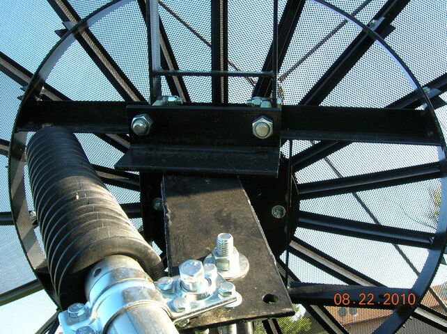
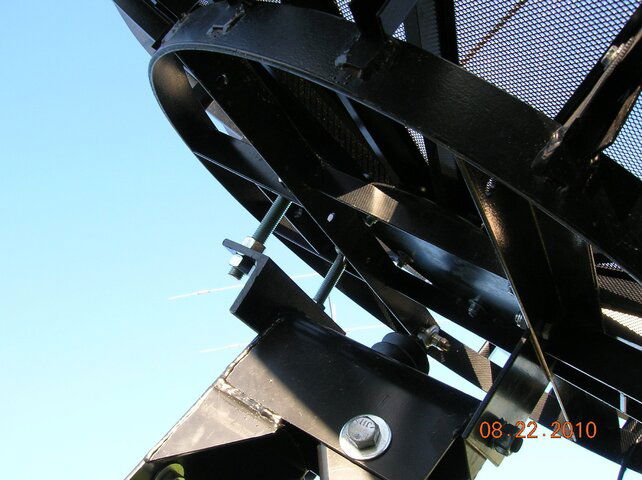
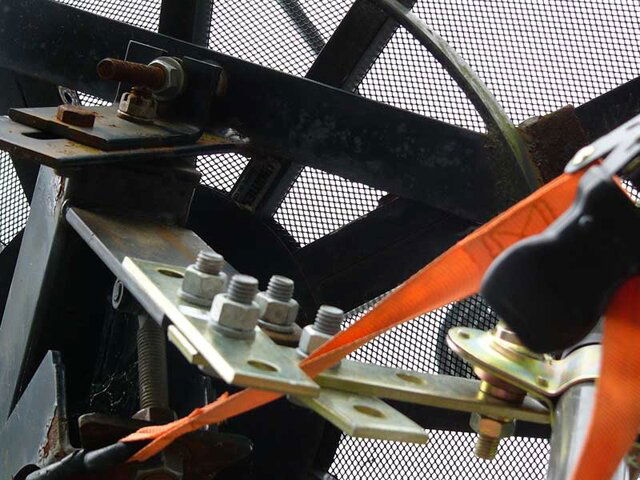
and on your dish, your pivot point and connect point for your actuator do look very close.
i bet a piece of angle iron bolted to the back of your mount to extend it out further would work great. you would likely see more accuracy and it would draw less current at the same time. one thing to remember when doing this is that if you move it out too far, you could loose some sats at the end of your arc, so it would be a good idea to get a long actuator.
also, i might add that i have never seen the von weise actuator use anywhere near the 2.75 amp max rating, even with the relay circuit and insane voltages being run into it.
Hope this helps,
Denny
 
Last edited:
SatelliteAV said:
If the ribs are too light weight, attach an angle iron arm to the ring and move the attachment point out one, two or more feet... The jack appears to be able to support at least a few additional feet of offset. You wouldn't believe the difference this modification will make in increasing the aiming accuracy and lifting capacity. I would guess that your motor would start reliably landing on the satellites!

I did that to a dish and it worked. Stick welders are fabulous LOL
 

Attachments

  • mod_bottom.jpg
    mod_bottom.jpg
    78.4 KB · Views: 138
  • mod_east.jpg
    mod_east.jpg
    93.2 KB · Views: 160
  • mod_top.jpg
    mod_top.jpg
    70.4 KB · Views: 133
If you want to experiment before welding, buy a few electrical splice plates SuperStrut, 3 Hole, Flat Splice Plate Fitting, 5-3/8" x 1-5/8" x 1/4", and a few 1/2" nuts and bolts.(I got mine at Home Depot) Then play with the positions. For me I got more range and less stress on the actuator.

I don't know if I'll have to weld a piece on. I'll have to see if bolting everything down will do the job and if it's stable then I'll leave it that way. I'll "report" back later. I plan to do the modification today even though it's another hot day (low 90's).

The nice thing about where the actuator is mounted (per vendor instructions) is that it gets the dish into position much faster than my Paraclipse.
 
Last edited:
johnnynobody said:
The nice thing about where the actuator is mounted (per vendor instructions) is that it gets the dish into position much faster than my Paraclipse.

Pick one.....
1. Speed
2. Accuracy
 
Pick one.....
1. Speed
2. Accuracy

I have been trying to collect information on rotor controllers because I'd like to build one. Use local power so a bigger motor can be used to get the speed up. The problem of over shoot is simple. Pulse width modulate the power to the motor. When you are within say 1-2 degrees of target, you drop from 100% to around 50%. And when within around .5 degrees, cut to 25%. Reducing when close, you shouldn't notice the slow down. Pulse width modulating the power allows you to control motor speed without impacting motor torque.
 
My first attempt at modifying the dish for the actuator failed. Apparently, a 1/4-inch thick copper bar isn't strong enough. It was looking good for awhile, though. Time for plan B.
 
I just installed some angle iron but I only bolted it on for testing. I found that I got an additional 1.8 pulse counts per degree, only. That's an additional 3.6 pulses between sats. That's not very impressive to me. The shaft was clamped down an additional 13 inches after the angle iron was installed. I could adjust it out an additional 13 inches but I can't justify the additional effort just to get an additional 1.8 pulses per degree. For 2 degree spacing of the sats, this would give me an additional 7.2 counts separation of sat positions (if I were to adjust out an additional 18 inches). And I didn't see an improvement in pointing stability, either. On the positive side, I got a greater view of the arc and the angle iron didn't bend.
 
Pulse width modulate the power to the motor.
When you are within say 1-2 degrees of target, you drop from 100% to around 50%.
And when within around .5 degrees, cut to 25%.
I once alluded to pulse-modulating the motor power, but nobody seemed to care.
Having experimented with model trains and my own pulsed supply, I can attest to their usefulness! - :up
We crept along the engine below the visible motion threshold.
And at full torque!
Only way to see it move, was with through closed-circuit video, with the camera aimed at a dust mote on one drive wheel!


The problem with moving dishes, is that there is currently no controller using PWM technology on the market.
And making one from scratch, would be a tall order.

edit:
I'd like to go one step further.
For an H-H motor setup on a BUD, I'd like to use USALS.
It'd just take setting up one variable: the number of steps per degree.
The rest is all left to the receiver to calculate (if I remember correctly)!
 
Status
Please reply by conversation.

Users Who Are Viewing This Thread (Total: 0, Members: 0, Guests: 0)

Who Read This Thread (Total Members: 1)

Latest posts