Did a search on this and got a bizzillion answers. So, thought I would just ask. I was thinking of making a power supply for the dead S9 I have from shop4fta. What I was looking for was what the pros think are the "best" voltages for switching the LNB from vertical/horizontal. Also how many amps or part of an amp do you need for most LNB's to work?

LNB V/H Voltage
- Thread starter RT-Cat
- Start date
- Latest activity Latest activity:
- Replies 66
- Views 15K
You are using an out of date browser. It may not display this or other websites correctly.
You should upgrade or use an alternative browser.
You should upgrade or use an alternative browser.
- Status
- Please reply by conversation.
The power supply is separate from the lnb voltage.
If the power supply is bad the whole receiver would be dark. Is this your case?
If it is just LNB voltage of your concern, it is controlled by a regulator located on the main board near the tuner and has an aluminum heat sink on it. Looks like a big power transistor.
If you can use a volt meter here are some checks you can make.
The regulator has three pins on it...
One has 24v. coming in from the main supply.
One has 0v. (ground)
One will have 13v. or 18v. coming out if the device is working properly.
These voltage regulators typically handle 1.5 amp of current, so your basic specs are there. I have an LM317T in my hand.
Vout= 1.2 to 37V
Cout limited to 1.5A
Absolute maximum ratings
15W
i/o voltage differential 40V
Vout= 1.2 to 37V
Cout limited to 1.5A
Absolute maximum ratings
15W
i/o voltage differential 40V
NO.The power supply is separate from the lnb voltage.
If the power supply is bad the whole receiver would be dark. Is this your case?
That "bad" S9 has voltage coming out to the LNB's, but there must not be any current. Nothing received.If it is just LNB voltage of your concern, it is controlled by a regulator located on the main board near the tuner and has an aluminum heat sink on it. Looks like a big power transistor.
If you can use a volt meter here are some checks you can make.
The regulator has three pins on it...
One has 24v. coming in from the main supply.
One has 0v. (ground)
One will have 13v. or 18v. coming out if the device is working properly.
Power the LNB's with my 920 and that S9 works fine. Not enough "power" to fire up the LNB's from the S9.
.
Maybe I'll open it up and take a look.
 :
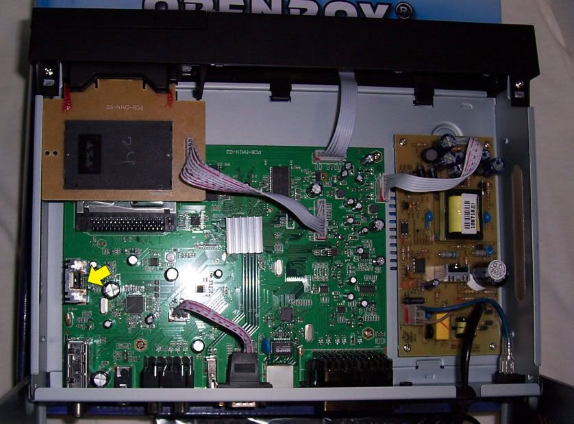
:If you do get inside, another thing to check is a small resistor right in front of the regulator (see yellow arrow in photo).
It looks like a tiny black square component and should measure about 200 ohms. If this has been over heated it will go high in value. It is possible to tack solder a new one right across the old one on the top side of the board.
This resistor is more troublesome than the regulator itself.
It looks like a tiny black square component and should measure about 200 ohms. If this has been over heated it will go high in value. It is possible to tack solder a new one right across the old one on the top side of the board.
This resistor is more troublesome than the regulator itself.
PLEASE LOG IN TO GET RID OF THESE ADS!
I've found my C bnd lnb will not switch to vertical until the LNBF voltage drops below 14v. and switches to horizontal a few 10ths below 16v. My 9200 and the S9 supply 14.3 volts for vertical. To high to switch the C band feed reliably*. My Ku LNBF's all switch to Vertical right around 15 volts. *reason I put a diode inline, to switch polarity on C band.What I was looking for was what the pros think are the "best" voltages for switching the LNB from vertical/horizontal.
Maybe, one day, when not so lazy, I'll look in there and change the resistor to lower the voltage.
LM317data sheet
May be the regulator. I opened the receiver up last night and get 19.1V to ground on left pin, 0V on center, and 0V on right pin. That does not match up too good with your other post.If you do get inside, another thing to check is a small resistor right in front of the regulator (see yellow arrow in photo).
It looks like a tiny black square component and should measure about 200 ohms. If this has been over heated it will go high in value. It is possible to tack solder a new one right across the old one on the top side of the board.
This resistor is more troublesome than the regulator itself.
Nice picture Jim. I looked the unit over and "ya gota" pull the whole board out to change that regulator. Oh, well, it can't be any worse than tearing this laptop I am on completely apart to change a bad power connector on it this last Fall.

The only time I need voltage switching for V/H is when I go to a satellite that one of the fixed dishes is set at. If I go C-band, that is on the 8ft BUD and the polarator takes care of V/H setting.I've found my C bnd lnb will not switch to vertical until the LNBF voltage drops below 14v. and switches to horizontal a few 10ths below 16v. My 9200 and the S9 supply 14.3 volts for vertical. To high to switch the C band feed reliably*. My Ku LNBF's all switch to Vertical right around 15 volts. *reason I put a diode inline, to switch polarity on C band.
Maybe, one day, when not so lazy, I'll look in there and change the resistor to lower the voltage.
LM317data sheet
Jim, I took my high power magnifier and took a look at that resistor. It has 3 (?) solder points. Rather an "odd" resistor to me.If you do get inside, another thing to check is a small resistor right in front of the regulator (see yellow arrow in photo).
It looks like a tiny black square component and should measure about 200 ohms. If this has been over heated it will go high in value. It is possible to tack solder a new one right across the old one on the top side of the board.
This resistor is more troublesome than the regulator itself.
RT.
Well, yes, but as I stated it has three legs on it. New type with 3 solder points??? Never saw one like that.Ted,
Did you measure the resistor?
I get nothing across any two legs. ????? AS if it was "open."
RT.
PLEASE LOG IN TO GET RID OF THESE ADS!
A transistor has 3 legs.......
Place the receiver on a vertical channel and check the power on the 3 regulator legs. Place the receiver on a horizontal channel and check the power on the 3 regulator legs.
Check the opposite side of the center leg resistor for voltage. This resistor may have failed.
Place the receiver on a vertical channel and check the power on the 3 regulator legs. Place the receiver on a horizontal channel and check the power on the 3 regulator legs.
Check the opposite side of the center leg resistor for voltage. This resistor may have failed.
Last edited:
I couldn't tell from the photo, but often those big three-terminal regulators *can* changed from the top of the board only, if getting to the bottom side is all that big a hassle.
- get a replacement part.
- cut the legs off the old one, up near the black plastic body.
- unbolt 'n throw away the old regulator.
- use tweezers to pull out the old legs when you heat the board.
- a solder sucker may help.
- drop the new part into place and bolt it to the heat sink (re-use old hardware, and apply a little heatsink grease).
- solder the three leads where they go through the board.
- not guaranteed to be 100% bug free, but probably 99% so.
(only thing I can think of is if the leads are so long, they go through board and short to the chassis below)
The arrow in my photo my be off slightly as I placed it from memory (um.. I'm 60) last time I was in there. I'll have to open mine up again today and take a fresh look. But meantime, it only has two legs. You must be looking at a transistor. The little two legged square resistor is near by.
EDIT:
The arrow is correct, hard to see in my photo that the resistor (much smaller than the three leg transistor) is in line with the center leg of the regulator and should measure 220 ohms. Not the 200 or 600 I have mentioned in the past. As for the regulator, from left to right lets label the pins 1-2-3. Voltage should measure...
Horz. channel
1=18v output
2=20v control v.
3=25v input
Vert. channel
1=13v
2=15v
3=25v
I'll take some macro pictures today and write up a "how to" procedure.
I will post this in a new thread later today or tomorrow. Right now my wife is making me go to a Super Bore party.")
EDIT:
The arrow is correct, hard to see in my photo that the resistor (much smaller than the three leg transistor) is in line with the center leg of the regulator and should measure 220 ohms. Not the 200 or 600 I have mentioned in the past. As for the regulator, from left to right lets label the pins 1-2-3. Voltage should measure...
Horz. channel
1=18v output
2=20v control v.
3=25v input
Vert. channel
1=13v
2=15v
3=25v
I'll take some macro pictures today and write up a "how to" procedure.
I will post this in a new thread later today or tomorrow. Right now my wife is making me go to a Super Bore party.
Last edited:
Not really, just lots to take apart. Already have the board out of the case.I couldn't tell from the photo, but often those big three-terminal regulators *can* changed from the top of the board only, if getting to the bottom side is all that big a hassle.
OK, in line, found it. That resistor reads 155 ohms across the legs. But, I have always read somewhere you should have one leg unhooked from the board to get a correct reading of a resistor. While on the board "other" parts can make it read differently......the resistor (much smaller than the three leg transistor) is in line with the center leg of the regulator and should measure 220 ohms. Not the 200 or 600 I have mentioned in the past. As for the regulator, from left to right lets label the pins 1-2-3. Voltage should measure...
Horz. channel
1=18v output
2=20v control v.
3=25v input
Vert. channel
1=13v
2=15v
3=25v
.
Before I pulled the circuit board the readings were:
1=19.2V to ground.
2=0V
3=0V
Same readings H or V
The 220 ohms is an "in circuit" reading on a normal working receiver. When my resistor was overheated it went high in value, something like 1.2k ohms. Your being lower tells me adjacent components are pulling it down. Probably the regulator. The o volts on two pins also indicates that. I think you are getting close.
PLEASE LOG IN TO GET RID OF THESE ADS!
Changed the regulator today. Got all the voltages that have been listed now. Still won't power the LNB. ???
RT.
RT.
Ted,
How did you get the replacement regulator so fast? Disappointing that it isn't working yet. I could throw out a bunch of questions if you want any more help trouble shooting it, or you could bring it up to Traverse City some time.
How did you get the replacement regulator so fast? Disappointing that it isn't working yet. I could throw out a bunch of questions if you want any more help trouble shooting it, or you could bring it up to Traverse City some time.
Well, more like Pixl's than my bad numbers.Listed by you or listed by Pixl ?
Now I have 13.2 Volts on Vert
and 18 volts on Horz
But still will not power LNB.
Turn off LNB power and power from another source, works fine, picks up stations.
RT.
PLEASE LOG IN TO GET RID OF THESE ADS!
- Status
- Please reply by conversation.
Similar threads

- Replies
- 8
- Views
- 659
- Replies
- 4
- Views
- 932
- Replies
- 14
- Views
- 930
- Replies
- 15
- Views
- 408
Users Who Are Viewing This Thread (Total: 0, Members: 0, Guests: 0)
Latest posts
-

-

-
I
-
TMicrosoft Continuing to Add Requested Features
- Latest: TWiT Tech Podcast Network
-
L