Modify Powered 3x4 Multi-Switch - Show Me

Status
Please reply by conversation.

linuxman

SatelliteGuys Pro
Original poster
Jul 16, 2006
3,903
16
North West of St. Louis, MO
Went down to Skywalker today and told my buddy there that the LNB power boosters had not worked as well as I wanted because of the extra connection involved and the signal loss that comes with it.

I asked for a powered 3x4 multi-switch. Told him what I was trying to achieve with standard C-Band/Ku Band LNBs and their need of more than 15V.

I told him about the modification my neighbor had done on the other power boosters and he understood.

We put a meter on it before I left and it only showed 11.9 V on the 13V side. So I asked if it were possible to modify this switch, and he said sure.
just cut the 13v trace on the board and run a jumper from the last known source of the 18V
.

My neighbor across the street was busy tonight and won't be available until tomorrow evening.

I need to learn how to do this myself. I think it can be done pretty simply. I don't want to interfere with the signal, or mess up the switching which I think is all done on the other side of the board on the receiver input side.

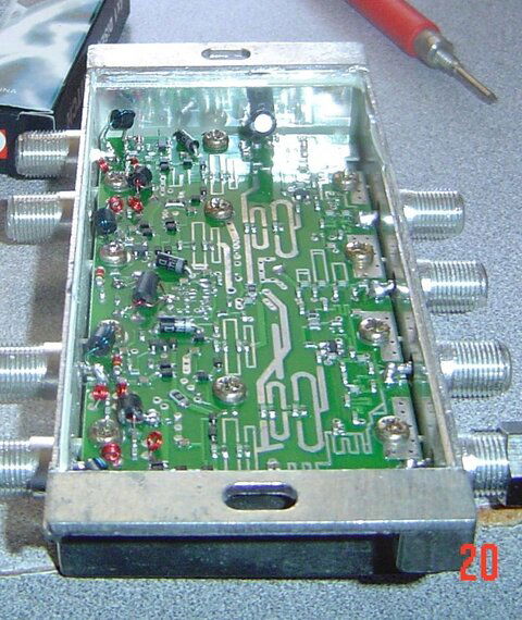
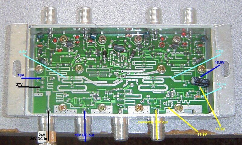
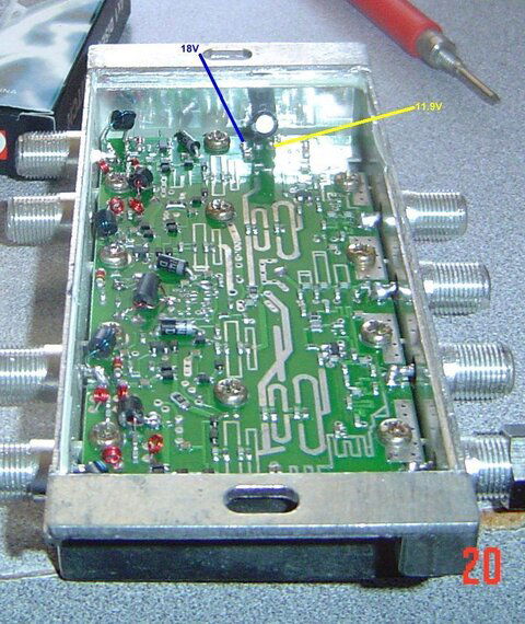
Here are pics with voltages marked.

Where do I "cut the trace" and where do I run the jumper from?
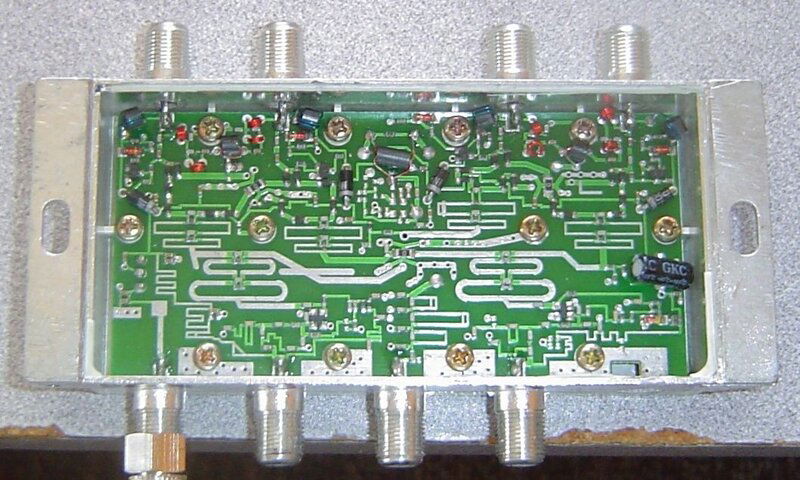
board-inside.jpg board-inside-side.jpg board-inside-w-voltages.jpg board-inside-side-where-18-becomes-12v.jpg

Just point me in the right direction. :)

Thanks for your help!
 
" Show me? "

Geez! Kiss my foot! - :D

Okay, here's my suggestion:
- see the three large round pads to the left in the 3rd picture, labeled 18 and 27 volts?
- the pin in the middle should be ground, so unpower the unit can check the middle pin to the case for continuity
- I'm pretty sure that's a 3-pin voltage regulator with unregulated voltage in on one side, regulated out on the far side, and center ground.
- check for continuity from the 18 volt pin on the left to the similar one on the right of the board - should be a short
- I think the three pins on the right are another regulator.
- they come in 12 and 18 volt versions.
- see the solder pad below (south of) the lower pin on the right regulator? you have it marked in yellow as 11.9 volts
- use a utility knife and cut that pad lose from the regulator pin.
- double check with your ohm meter to make sure you got it isolated.
- don't cut into the green fiberglass board, just nick the copper trace.
- now, connect an insulated jumper wire from the top (northern) pin on the right regulator (source of 18 volts) to the pad you just cut lose.
- fire it up and see if it smokes.

Second choice? Wait for tomorrow night when your engineer neighbor is free.
I really like him, and know he'll do a fine job.

edit:
Here's a link to a picture showing both the voltage regulator part, and the way it's usually wired into a circuit.
You see small bypass caps on the input and output, and in some applications a large capacitor on the input side.
 
Last edited:
Well I tried!

I have the solder glob completely removed from the south pin of the regulator. Only the pin itself is still attached to the "ring", and there is a trace coming to that ring from the "West" that powers another section of the circuitry.

I have what appears to be no linkage between the south "terminal ring" and the ring next to it which continues the 13V side of the circuit. Looking at it through a magnifying glass, it appears to be completely separate and what looks like the Grand Canyon between them. Yes, I know you said not to dig into the board.

I still can't break continuity between those two "rings". There may be something on the other side of the board that links them. Just don't know.

I have been at it for over 2 hours and not yet ready to patch back in the 18V power.

I will have to wait for my engineer buddy to get home from work. :(
 
My engineering neighbor came over and fixed up two of my powered multi-switches.

He gave me an introduction on how to cut the trace, told me I needed a new meter, a better soldering iron, and to make a work area that I can utilize my florescent ring magnifying glass, smaller guage wire for patching, and an exacto knife. Then I would be ready for some experimenting.

You were pretty close on where to make the cut Anole. He actually moved past the surface mounted capacitor which is just "South" of the big black capacitor and made his cut in the trace there. You can see in the picture the little brown spot just above the red patch wire, and the little white cut is just below the red wire.

Patched it in, and now have 18V on the vertical side. This should gain back all the signal I lost with having the extra connection with a regular multi-switch and separate LNB power booster.

He said the switching and signal should not be hurt in any way.

Here is the picture.

bypassed-regulator-capacitors.jpg
 
Congratulations.
That's a good mod for this particular application.

I told you I liked that guy.
He's right on top of things.
And he didn't have to work from 1800 miles away with a fuzzy picture. - :eek:
Having it in your hands where you can examine it from all angles really helps.
At least you didn't have to remove the PC board to get to the other side.

Just don't ever try to use these switches for their regular applications.
I can see it all now , wondering why both V and H give the Horizontal transponders. ;)

(I'm just waiting for someone to suggest you put in a slide switch...) :)
 
Just don't ever try to use these switches for their regular applications.
I can see it all now , wondering why both V and H give the Horizontal transponders.
I would agree, but I can think of several applications where they would work just fine.

One would be the separate output Primestar LNBFs, especially if trying to use it with a DVB PCI card. The device of choice in that application is a multi-switch already, and having the power boosted on those old LNBFs on both sides would benefit them immensely. Once the switch is made, the right polarities would still come in fine.

But you are correct, the primary application would be for dual C-Band feed-horns, dual Ku-Band feed-horns, or dual C and Ku orthomode feed-horns in combination with standard non voltage switching LNBs. :)

The modification is very simple, and these can be returned to their ordinary purpose very easily.
 
They work!!! :cool:

Got the signal back that was being lost with the extra connection of the LNB power boosters.

Both H and V are getting their 18V of power needed, and the powered multi-switches work fine with my Twinhan 1020a.

Picture me jumping up and down happy!! :)
 
Photos, please. ;)
Yea, I want to see you off the ground... no, not on a ladder, and not on the roof. :D

And you owe us a helicopter shot of that roof, too.
Just post it over in the Dish Farm thread. That should raise some eyebrows! :eek:


So, the power boosters lost signal, eh?
Well, by cutting them out of the loop, you seem to have gotten it all back.
Anxious to hear some across-the-arc signal readings from your new baby, soon.

Don't know if your neighbor pointed it out, but if you ever decide you need 20, 22, or 24 volts on those LNBs, you can mod for that, too.
 
And you owe us a helicopter shot of that roof, too.
Just post it over in the Dish Farm thread. That should raise some eyebrows!
If I had a way to get a shot without costing an arm and a leg, I would do that. :)

So, the power boosters lost signal, eh?
It wasn't the boosters that lost the signal, it was the extra connection. Just one too many.
Well, by cutting them out of the loop, you seem to have gotten it all back.
Anxious to hear some across-the-arc signal readings from your new baby, soon.
Well for starters:
G11 - 91W Ku 12060 V is at 90% SQ
G11 - 91W C-Band 3720 H is at 90$ SQ
Hispasat 30W Ku 11884 V is 60% SQ
Hispasat 30W Ku 12172 H is at 80% SQ
G10R 123W 11720 V is at 75% SQ
G10R 123W 11805 H is at 99% SQ

All readings taken with the Pansat 3500.

That's all I can remember off the top of my head and I don't have it hooked up any longer to take further readings.

Suffice it to say, I am very very happy. :D

BTW, I figured out how to use the Sat Buddy 2 to adjust the skew using the multi-switch to choose the polarity. :)

Very nice and very accurate. :)

EDIT:
Don't know if your neighbor pointed it out, but if you ever decide you need 20, 22, or 24 volts on those LNBs, you can mod for that, too.
You are right, it would be very easy to do. Just change the regulators at both ends. :eek:
 
good work

Just change out the one regulator on the left.
And, we might be able to do it without removing the PC board, if it were that important.
 
Just change out the one regulator on the left.
And, we might be able to do it without removing the PC board, if it were that important.
I thought about that after I wrote the edit, and you are correct. I would only need to change the one regulator.

I don't think it is necessary to make any changes. The voltage supplied falls well within the specs of the LNBs. :)
 
can someone take a photo or clarify exactly where the trace is cut. I can see the jumper wire pretty well. I can see you are just taking the 18v input from the regulator and passing on to the regulator's output with a jumper and isolating the output of the regulator so its 11.9v goes no where.

in the photo i can't see exactly where the trace is cut but approximately.
 
Status
Please reply by conversation.
***

Users Who Are Viewing This Thread (Total: 1, Members: 0, Guests: 1)

Who Read This Thread (Total Members: 1)

Latest posts