Need to wire up a c band mover/arm

Status
Please reply by conversation.

ken2400

SatelliteGuys Pro
Original poster
Sep 4, 2004
1,309
144
Central NY State
I am trying to get a C band arm going . It has four wires. Two I know are for the 36 volt motor and are like 16 gauge. The other two or three I do not know about. A sensor, 5 volt , and ground I think. Is there a standard color code for them?

Thanks
 
Depends on the cable. Personally, I've been using four strand water sprinkler wire for some time. the four wires are different colors. I do go to the motor with stranded, flexible wire, using wire nuts off of a junction box near the dish.

The dish mover unit you have, like a Gbox for instance, will say in its manual which connectors go to the motor and which to the reed switch/counter.

You need to be more specific as to what motor you have and what dish mover.
 
easiest to open the motor an take a look see which wires are used for what for the sensor. Every cable mfg. used different color wires so there's no standard.
 
Vbox X, which is about half the price of a Gbox has 4 terminals. Two are for motor power and the other two are for the reed switch, which does counts for positioning of the dish. The larger wires are for the motor as most are 24/36 volts. Reed switchs on the other hand are usually much lower voltage, ie, like 5 volts and can be easily damaged if 24/36 volts are applied through them accidentally. Since most wiring harnesses have color codes, you need to make sure you match what you use on one end to the other voltage wise.

And as was mentioned, be a little more specific with info as it does help detirmine what you need to do.
 
I am trying to get a C band arm going . It has four wires. Two I know are for the 36 volt motor and are like 16 gauge. The other two or three I do not know about. A sensor, 5 volt , and ground I think. Is there a standard color code for them?

Thanks

I use a Gbox to control my dish position. There are four wires. Two heavy gauge wires should be used to connect to the motor. Currently I use TV rotor 5 conductor flat ribbon type. To wires are used for the motor negative connection and one for the positive connection. Polarity is important. Reversed actuator motor wiring will cause the motor to turn in the opposite direction. Before you get started make sure you know which direction the motor should turn when you want to go east (or west). According to my calculation, the motor wire is far too small. It works but sometimes the dish gets stuck. Larger motor wire would provide less voltage drop from the Gbox to the motor and generate more torque to reduce the tendency to get stuck.
My GBox provides two connections to the micro-switch and does not care how the micro-switch is wired; either way will work. The micro-switch provides the actuator count to the GBox. My actuator provides 48 pulses/inch or inversely, one pulse for every 1/48 inch. Other actuators will vary; it may be 32 pulses/inch for example. The Gbox count is a function of actuator length and is a linear function. The count will increase when the motor is turning one-way and will decrease when turning in the opposite direction. This trick saves quadrature decoding circuitry and the nonvolatile Gbox memory saves the count. However it is not a linear function between the axis of rotation and the actuator length. Dish mechanics determine the relationship. It may be close to linear but it is not exact linear. In my case it is not even close to linear; but can fit a fourth order function with a crude degree of predictability.
Obviously you may have a far different system than mine. Read your manual!
 
I am trying to get a C band arm going . It has four wires. Two I know are for the 36 volt motor and are like 16 gauge. The other two or three I do not know about. A sensor, 5 volt , and I think. Is there a standard color

Thanks

ken2400

I have a G-Box hooked to a 36V actuator. The dish is 200 feet from my receiver. I used 6 wire sprinkler wire from Home Depot.

Knowing the motor draws a lot of current, I used 2 wires for each of the motor leads, and 1 wire for the sensor leads.
I used:

Red and the Brown wires to Motor +
Green and the White wires to Motor -
Blue wire to Sensor +
Orange wire to Sensor -


There really isn't anything magic about the colors used... but it is vital that the colors are consistent at both ends. Here's a tip: be sure to write down what colors you used and keep them around for troubleshooting in the future. I wrote mine down in the back of my G-Box manual.

===
Bill
 
Thanks for the info.
The arms are superjack 2X HB
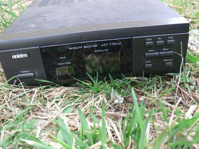
The moving that works for me, when it feels like it, is a Uniden 7700
I was able to get the second arm moving with two wires, the power ones.
It move a little be then stops. I assume because I did not hook up the sensor wires? It moves both ways so life is good.

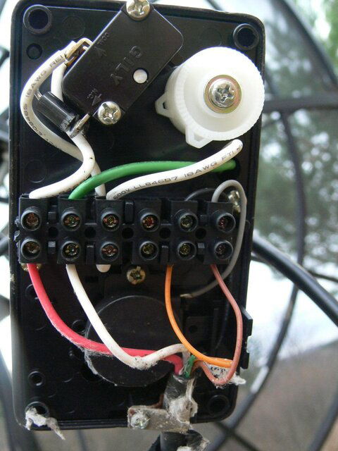
P1120298.JPGP1120299.JPGP1120300.JPGP1120301.JPG
 
I... Polarity is important. Reversed actuator motor wiring will cause the motor to turn in the opposite direction. ....

I face south looking at my tv, so I used this to wire my old dish to be more intuitive - pressing the remote button on the west side of the Gbox remote to move the dish west, and the east side button to move it east. That worked nice on my first big dish, with Superjack actuator.

The Birdview I have now won't let me do that. You can only wire it one way. So now, west is east and east is west.

It's better when it's intuitive. Still mix it up sometimes.
 
Polarity is important. Reversed actuator motor wiring will cause the motor to turn in the opposite direction.
Every time I replace an actuator, this happens. Even if I try to second guess my first guess, because I "just know" that the first guess will be wrong. Have to unscrew the wires and switch. I even filled out the drawing in my Drake manual to show which colored wires go where, but do I ever use it when installing? Heck no... Too much in a hurry to get the thing installed that I end up wasting time switching wires instead of using that time to consult the drawing. You'd think I'd learn by now...:rolleyes:
 
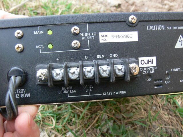
I use the superjack also. The wiring in your picture shows that the motor leads are the red and white. The Orange and Brown are the sensor leads and the sensor is a reed swtch, which will connect to "SEN" & "GND" on your UST7700. It does not matter which of the orange or brown go to "SEN" or "GND". The red and white go to the + & -, connect so that the motor moves the dish east when you choose east on the UST7700, if it moves west, switch the leads.
Good Luck!
 
Status
Please reply by conversation.

Users Who Are Viewing This Thread (Total: 0, Members: 0, Guests: 0)

Who Read This Thread (Total Members: 2)