TEK figures were close since I came up with a focal distance of 52.71 inches. With the existing pre-drilled holes (5 of them on each panel), I could only get out to 51.5 inches. So, my options are to drill more mounting holes or get longer support rods. I just happen to still have my old Paraclipse rods that are longer than the TEK rods. I'll give them a try. Anyway, calculating the focal distance gave me the opportunity to do the string test also. Surprise, surprise, surprise! The string test is good.It can't be wrong to check yourself!
See e.g. this thread: Dish Specs, Trust But Verify!
Greetz,
A33

new 1.2 meter dish and 12 footer
- Thread starter WhiteBeard
- Start date
- Latest activity Latest activity:
- Replies 250
- Views 30K
You are using an out of date browser. It may not display this or other websites correctly.
You should upgrade or use an alternative browser.
You should upgrade or use an alternative browser.
SatelliteGuys Fund Raiser
100%
- Total amount
- $885.00
- Goal
- $350.00
Donation ends:

You better make them length-adjustable.or get longer support rods.
Cut them at the 1/2 way point, and get some lengths of slightly larger tubing to fit them. Just long enough to keep them straight and tight. Sort of like a smaller straw, inside a larger straw. Or think of the design like an old portable FM radio telescoping antenna rod. That way you can telescope each support rod, and once you get the proper distance from the center plate, you can drill holes through each end and fix them with bolts.
That way you don't need to search out and manufacture completely NEW full length rods.
Or, some long bolts used as stand-offs down at the dish part of the mount. You can double-nut and washer them. They only need to be a couple inches long to extend the support rods a little further. So, the support rod ends will bolt onto the bolts you install, and thereby offset the support rods above the surface of the dish, just long enough to get the distance you need dialed in.
I'll do that as a last resort. There are 5 pre-drilled mounting holes on each panel that I can use to adjust the feed location. But, the double nutting and washering is something that I'm considering if I need to get a more accurate feedpoint. I don't know how accurate it needs to be but I suspect that being within a 1/4 inch out to be good enough. I'll endevour to get within a 1/8 inch though.Cut them at the 1/2 way point, and get some lengths of slightly larger tubing to fit them. Just long enough to keep them straight and tight. Sort of like a smaller straw, inside a larger straw. Or think of the design like an old portable FM radio telescoping antenna rod. That way you can telescope each support rod, and once you get the proper distance from the center plate, you can drill holes through each end and fix them with bolts.
That way you don't need to search out and manufacture completely NEW full length rods.
Or, some long bolts used as stand-offs down at the dish part of the mount. You can double-nut and washer them. They only need to be a couple inches long to extend the support rods a little further. So, the support rod ends will bolt onto the bolts you install, and thereby offset the support rods above the surface of the dish, just long enough to get the distance you need dialed in.
Not confuse anyone but my choice (buttonhook feed) was to put three 2 1/2" stainless machine screws through the scalar with lock nuts. Then using 2 machine nuts for each of the 3 screws to position the scalar at the approximate length from dish center. And then do my final tweaks by lengthing/shortening the screw position.
Maybe that makes sense. It sure made for less twisting and turning and in and out of the LNBF to peak signal.
Maybe that makes sense. It sure made for less twisting and turning and in and out of the LNBF to peak signal.
PLEASE LOG IN TO GET RID OF THESE ADS!
That's another idea to consider. Sounds like it's a similar idea that my Paraclipse had with the knurled nylon screws with hollow centers where adjustment bolts went through. Difficult to adjust though.Not confuse anyone but my choice (buttonhook feed) was to put three 2 1/2" stainless machine screws through the scalar with lock nuts. Then using 2 machine nuts for each of the 3 screws to position the scalar at the approximate length from dish center. And then do my final tweaks by lengthing/shortening the screw position.
Maybe that makes sense. It sure made for less twisting and turning and in and out of the LNBF to peak signal.
This is a response I got at tvrosat:
"You will find that some LNBFs/feed horns work best at 51.5", some at 52" and some at 52.5". This is because every LNBF/feed horn has a slightly different phase center and it must coincide with the dish focus for maximum signal gain."
Probably true. If all this fine tuning is only going to vary the reception by 1 dB when I'm already getting 14 dB C/N then I'll just take whatever as-is and forego the hassle of fine tuning.
I find that for C Band at least that little bit more dB is the difference between receiving a channel and not for weaker tp's. Sometimes .5 dB.
As for scalar position, it seems to be the difference between narrow beam signal and lowered signal overall as you tweak it in and out from dish center. And was the reason I opted for long screws for tweaking.
Independent of LNBF position.
One sat in particular I found that different transponders would require a "bump" of the ASC 1 to peak signal.
Case in point is 131W. I ended up modifying the satellite.xml to have a 131W and 131W* name that had the strongest tp's for each position in each list. No more hitting the W-E buttons.
But then again, that's me.
PLEASE LOG IN TO GET RID OF THESE ADS!
I got my focal point to 52 inches and I'll go with that for now. Telescoping supports seems like a nice idea but I don't know if I'll go to that "extreme". I don't want this to be like buying a car and then modifying it to try to make it "better". Too bad I can't afford a properly engineered antenna just like I can't afford a properly engineered car.
I had to fix a Gbox so that I could continue with this installation. Found the actuator plate also. It doesn't look like the images I've seen though. I let the Gbox run all day since the transformer voltages were higher (20V vs 18V and 40V vs 36V). The display is brighter and I can move the dish but I won't do the alignment until tomorrow. I need to clean up the transformer install in the Gbox but it'll have to be an open case until I can do something different. The transformer is much larger than the original. Maybe I'll post images of the dish tomorrow.
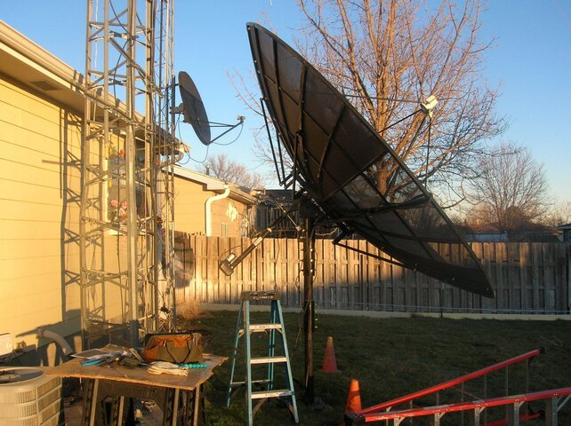
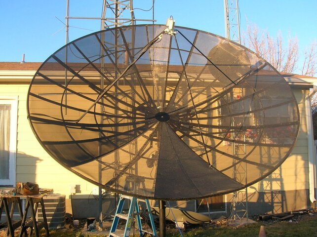
I put the new TEK 12 footer online this afternoon. I was surprised how accurate my alignment was. But I still need to fine tune the dish. I think it's true south is a little off to the west. I was watching programs but then the dish mover quit after the sun went down. I think it's some kind of connection problem. A project for tomorrow. But I did get 97W to 113W programmed in. Photos below
Attachments


Turns out that a diode shorted out for the actuator power circuit (36V) in the Gbox. First the transformer and now this. I don't have a complete schematic (missing the power supply circuit) for the Gbox so I'm guessing that's a diode that's part of a full wave rectifier circuit since there are 4 diodes spaced close together. It's an RL207 diode rated for only 2A forward current. I'm thinking of replacing all 4 with 10A10 diodes. It's overkill and I have to buy 20 pieces. And they might not fit the holes on the board. But the package is only $6 at Amazon. I just hate getting too much extra because I'll never find them again when I need them. Where's a Radio Shack when you need one? And what will break next? In the meantime, I have one of those PR1200's coming.
These are used to keep the dish in stationary mode to watch just one satellite with no motor.
Sent from my LM-G710VM using the SatelliteGuys app!
Now for my next question. I have 2 pieces of angle iron that came with my package and I don't know what they are for. They have a hole on one end and 2 holes on the other end.
Sent from my LM-G710VM using the SatelliteGuys app!
PLEASE LOG IN TO GET RID OF THESE ADS!
Arrgh, why didn't I think of that earlier! Too many things on my plate. Who says retirement is boring?These are used to keep the dish in stationary mode to watch just one satellite with no motor.
Sent from my LM-G710VM using the SatelliteGuys app!

10 footers are not any different. I've spent hours trying to get it the best it can be from 34.5 to 139w. A certain spot is better until 58w. Then the dish works the best around 107w by being a tad bit higher. The dish needs to be a little higher still for the West satellites like 139w. Trial and error and settle in a spot that tries and works the best everywhere.
Sent from my LM-G710VM using the SatelliteGuys app!
I got my focal point to 52 inches and I'll go with that for now. Telescoping supports seems like a nice idea but I don't know if I'll go to that "extreme". I don't want this to be like buying a car and then modifying it to try to make it "better". Too bad I can't afford a properly engineered antenna just like I can't afford a properly engineered car.
Sent from my LM-G710VM using the SatelliteGuys app!
I have a bracket that came with the dish and I was told it is for an elevation actuator. I have an 18" actuator laying around that might be good for that but I'd have to get another dish mover. Sounds like that would take a bit of time to set up. Too many things that I want but so little money......10 footers are not any different. I've spent hours trying to get it the best it can be from 34.5 to 139w. A certain spot is better until 58w. Then the dish works the best around 107w by being a tad bit higher. The dish needs to be a little higher still for the West satellites like 139w. Trial and error and settle in a spot that tries and works the best everywhere.
Sent from my LM-G710VM using the SatelliteGuys app!
Got my PR1200 today. Plugged it in and found that the dish still won't move. I got ERR2 going east or west. Continuity check of cable wiring turned out good. So, I took the PR1200 to the pad. It did move the dish a very short distance before I got ERR2 going east or west. Looking inside the actuator, the gears and reed magnet moved for a short time. I did a reset on the PR1200 to make sure that there weren't any limits set. Still no-go. I disconnected the actuator arm and found that the dish moved easily. I was going to continue working in the dark but decided to quit for the night. I'm going to disconnect the actuator tomorrow and see if it'll move OK when not connected to the dish. I suppose it could be the reed switch but I did see pulses with my digital voltmeter (not the best way to check but you do what you can with what you have). I wish I had a variable DC supply that goes at least to 40 VDC@30A with a current limit feature.
Try with just a 12volt car battery hooked to the actuator motor, and see if that moves it freely. 12 volts is enough, though it'll move very slowly if good.Got my PR1200 today. Plugged it in and found that the dish still won't move. I got ERR2 going east or west. Continuity check of cable wiring turned out good. So, I took the PR1200 to the pad. It did move the dish a very short distance before I got ERR2 going east or west. Looking inside the actuator, the gears and reed magnet moved for a short time. I did a reset on the PR1200 to make sure that there weren't any limits set. Still no-go. I disconnected the actuator arm and found that the dish moved easily. I was going to continue working in the dark but decided to quit for the night. I'm going to disconnect the actuator tomorrow and see if it'll move OK when not connected to the dish. I suppose it could be the reed switch but I did see pulses with my digital voltmeter (not the best way to check but you do what you can with what you have). I wish I had a variable DC supply that goes at least to 40 VDC@30A with a current limit feature.
PLEASE LOG IN TO GET RID OF THESE ADS!
Similar threads
- Replies
- 4
- Views
- 941
- Replies
- 8
- Views
- 587
- Replies
- 34
- Views
- 1K
- Replies
- 9
- Views
- 1K