Pendragon vs. the Birdview

Status
Please reply by conversation.

pendragon

SatelliteGuys Pro
Original poster
Oct 13, 2008
1,101
66
A few days ago in another thread several of you offered me great help and advice regarding the potential harvesting a Birdview solid I spotted on Craigslist:

http://www.satelliteguys.us/c-band-satellite-discussion/264089-birdview-motor-pole-questions.html

A friend and I launched the attack on Monday. It was an easy job, other than I forgot to bring wasp spray. Between squirting penetrant on them and swatting with newspapers, we managed to decimate the major part of the town's wasp population without any successful countercharges on us. We lost track of the number of nests we emptied from the motor housing and feed.

Because I had previously decided to mount this to a wall, and because we could see the classic Birdview pole indents below the ground, there seemed no reason to dig out the concrete and thus we chopped the pole at ground level. I plan to follow phlatwound's advice and weld the Birdview tube inside a 6" schedule 40 pipe to extend it to the proper length. The owner probably would have been ok with simply ridding her yard of the dish, but as she was a recent Army wife transplant, I gladly gave her the $75 she asked in the ad. She had been very gracious in answering several rounds of questions, confirming measurements, etc. The dish is in great shape, with only one strut snapped at where it attaches to the dish. More on that later.

The motor housing was a disgusting mess of dead insects and other debris, of which I have only removed the first few layers. I was a little disappointed to find this dish only had the original multi-turn potentiometer position sensing, but having read the extensive threads here on such matters, I had assumed this would have to be dealt with either way.

When I re-read the material, my eye was caught by a post by bryan.lynch several years back:

http://www.satelliteguys.us/124870-birdview-reed-sensor-kit-2.html#post1234794

Bryan found a rotary encoder on the cheap and proposed using this instead of the traditional magnet wheel/reed switch approach. While at that time he planned to do something with this part, as far as I could tell neither he nor anyone else ever reported back about such a scheme. This sounded more fun to me that fabricating a magnet wheel. Yesterday the encoder and some odd parts arrived, and this morning I was a little kid on Christmas.

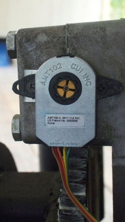
To summarize, the encoder is an AMT-102 from a company called CUI. It uses capacitive sensing to produce 48-2048 quadrature pulses per revolution. They also make an absolute position encoder which I may investigate some time down the road by attaching it directly to a polar axis shaft. There may be some issues with that, but the possibility of not caring about backlash sounds quite attractive. Still I would probably have to build my own GBOX-like unit to handle such a part. I digress.

The AMT-102 has a DIP switch to adjust the basic pulse rate. As the pulses are provided in quadrature, one can determine the shaft rotation direction. Unfortunately that is of no particular consequence for a GBOX/VBOX. However one can use the quadrature pulses to double the pulses rate. With the GBOX counting on both rising and falling edges, one can obtain 192-8192 pulses per revolution. Before proceeding with the motor itself, I bread-boarded a simple TTL XOR gate connected to an open-collector, high voltage buffer. The outputs of the encoder were wired in and the output connected to a GBOX. When set to the lowest resolution on the DIP switch (48 quadrature pulses), I measured about 200 counts for one turn of the encoder shaft. Perfect.

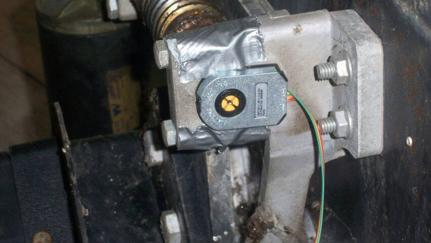
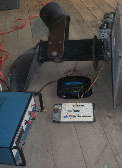
The next step was to transport the bread-board, power supply and GBOX to close proximity to the Birdview motor housing. The encoder kit has several shaft adapters. I chose the 3mm one which closely matches the worm gear shaft extension on which a small nylon gear used to live. This previously coupled to a larger gear driving the potentiometer. Rather than finalizing the mounting, I simply anchored the main part of the encoder with duct tape. I have attached a couple of photos of the setup.

Everything worked from the get-go. I centered the drive with a precision inclinometer and zeroed the GBOX. I ran motor until the half-moon gear was about to fall off the worm drive. I measured a motor angle of 80 degrees and a GBOX count of 5127, or about 64 clicks per degree (.016 degrees per click). At the same time I verified the GBOX could keep track of counts from -9999 to +9999 (nice). I doubt I would ever run a Birdview +/- 80 degrees because of the load being transferred to one or two teeth on the half-moon gear. This means one could adjust the DIP switch to 100 quadrature pulses per revolution for a resolution of 0.0075 degrees per click with a motor angle range of +/- 75 degrees, and be right at the point of wrapping around the GBOX counter. Of course this all is a bit silly as having such a resolution has very little to do with pointing accuracy. Still, bragging rights are worth something.

The next steps will be to wire-up a permanent circuit with some minor clean-ups and bypass caps, and drill and tap mounting holes for the encoder. First I'll have to clean and grease the gears. I will also have to provide a +5V source to run the circuit. That's available inside the GBOX, and I purchased a connector for the back of the GBOX so I can feed all five leads through that instead of dealing with the cheapo wire clamps on a stock GBOX.

Onto other matters.

I had read several people claiming the Birdview struts place the scalar about an inch too close to the focal point. My rough measurements confirmed that. As one of my struts was already broken, I looked into tapping it at something other than the stock value. It's not perfect, but I decided to tap the ends of all the struts at 7/16-14 after first cutting them down a few inches. I'll then twist on some bolt extenders and use about 4-6" of threaded rod so I can adjust the scalar position over a several inch range. Of course I'll have to drill the scalar plate out for this threading and use two nuts on each strut. This will change the adjustability of the Birdview scalar from being one of the worst imaginable to one of the best.

I've taken measurements of the Birdview scalar and have some minor concerns how well it will match a typical ADL or Chaparral feed. I'm not talking about the internal diameter, which has to be enlarged in any case, but of the field behavior. I may or may not model it before simply going ahead and reaming it out for grins because I don't want to adapt something else at this time.

Those who read my earlier thread may remember one of my targets is 37.5W, which requires a motor angle of 74 degrees where I live. Unfortunately the Birdview's half-moon gear will hit the back plate of the dish at about 65.5 degrees. I could chop out a small piece of this plate as it is not the actual dish surface itself to reach a larger motor angle. As I mentioned earlier, 80 degrees is really the absolute maximum the motor can be driven while still keeping a gear tooth or two meshed with the worm drive gear. If one lets the half-moon fall out of the worm, the pole mount hits at 85 degrees. So there may still be a chance for 37.5W on the Birdview, but I'm not worried either way because my other C-band dishes can steer to about 34W and my 1.8m Prodelin offset on an Ajak mount can barely hit 30W.

More to come as I continue.
 

Attachments

  • Encoder.jpg
    Encoder.jpg
    90 KB · Views: 484
  • POC Setup.jpg
    POC Setup.jpg
    67.7 KB · Views: 454
Sounds great-that BV will become better than new, with your level of expertise. Naturally we would all enjoy more pictures!
 
Sounds great-that BV will become better than new, with your level of expertise. Naturally we would all enjoy more pictures!

Ditto!

Can't wait to see where you end up with this project, and I am still hoping you come up with a homebrewed elevation adjuster for me to copy. The BV dishes are very balanced when they are loose and moving on the elevation pivot but having some sort of screw-type adjuster would be excellent.
 
Different time, different place.

Back in 2008 when we were writing that thread you linked, I didn't have a Birdview, nor a Gbox.
At the time, I thought the shaft encoder a wonderful solution.
But, with most users unable to even run a hall effect sensor in place of a reed switch, the extra complication didn't seem user-friendly.
Making an interface to work with all the existing Analog, 4Dtv, and V/Gboxes appeared wise.
Now, analog and 4Dtv receivers are no longer a consideration for dish-moving so a custom mover interface is more attractive.

It'll be interesting to see what you come up with for a one-of-a-kind sensor system.
I'm really looking forward to it. :up
 
When you say that your measurements of the scalar indicate that it is one inch too close to the dish, that makes me wonder.

I figured focal length was measured from the dish to the little lnb sensors in the lnb or feedhorn. The original BV lnb bolted on the back of its scalar. I have tried to keep that in mind in placing the position of the lnbs I use.

That stated, I get DVB signals great and S2 signals sporadically at best
 
I've taken measurements of the Birdview scalar and have some minor concerns how well it will match a typical ADL or Chaparral feed. I'm not talking about the internal diameter, which has to be enlarged in any case, but of the field behavior. I may or may not model it before simply going ahead and reaming it out for grins because I don't want to adapt something else at this time.

ive always supected that scalars should be made to match the dish they are installed on. one of the first dishes i scored was a huge 10 foot 8 piece aluminum dish. its scalar always baffled me. it was simply huge. probly 3 inches more in diameter than anything i have seen in the other 17 dishes i acquired. ive also always held your opinion as the tops when it comes to this hobby. your opinions always seems to be based on a spectrum analyzer and some scientific method. were you confirming my suspicions with your statement or was i misinterpreting your post ?

crackt out,.
 
When you say that your measurements of the scalar indicate that it is one inch too close to the dish, that makes me wonder.

I figured focal length was measured from the dish to the little lnb sensors in the lnb or feedhorn. The original BV lnb bolted on the back of its scalar. I have tried to keep that in mind in placing the position of the lnbs I use.

That stated, I get DVB signals great and S2 signals sporadically at best

On many modern FTA C-band feeds adjusting the focal "point" so it is say about 1/4" inside the feed mouth often results in the best reception. This depends on a lot of factors, so it's best left to the final alignment when you are trying to get every last drop of dB. Unfortunately with strut-based scalar supports, adjusting the feed to the best focal point without affecting the f/D optimization can be a nuisance. I'm trying to avoid that with my Birdview mods. When I get to that stage I'll publish some photos and provide more details.

I need to make more precise measurements, but when I calculated the focal distance based on the dish dimensions, I came up with about 40.9". The front of the scalar measured about 39.5" from the center of the dish. Even allowing for inserting the focal point a a bit inside the feed mouth, that's still more than an inch off. I want to be able to easily adjust this once I get everything up, hence the strut mods.
 
ive always supected that scalars should be made to match the dish they are installed on. one of the first dishes i scored was a huge 10 foot 8 piece aluminum dish. its scalar always baffled me. it was simply huge. probly 3 inches more in diameter than anything i have seen in the other 17 dishes i acquired. ive also always held your opinion as the tops when it comes to this hobby. your opinions always seems to be based on a spectrum analyzer and some scientific method. were you confirming my suspicions with your statement or was i misinterpreting your post ?

I believe we're basically on the same page. One really wants to optimize everything together - the dish, the scalar and the feed. Nowadays FTA C-band scalars appear fairly standardized, and hopefully the feed designs consider this. However this doesn't mean that assembly is well matched to the dish, as is your concern.

Birdview had the chance to optimize the whole package and perhaps they did so. I have doubts, however, looking at what is there. At the time the complexity of accurately modeling everything often meant it was easier to cut and try. That didn't always result in the best configuration. Nowadays there's more science and a bit less magic and art required, but that doesn't make it a cakewalk.

The problem at hand is what to do with a scalar and feed that were not designed for one another. Reaming out a Birdview scalar to fit a modern feed may result in a good mechanical fit, but not necessarily the best signal performance. My gut feeling, supported by a little hen-scratching, is a Birdview scalar with a modern feed will provide very good front-to-back rejection, perhaps at the expense of under-illuminating the dish. I'm considering mods to address this if it turns out to be the case, but these may cause difficult-to-determine side-effects. There are a few potentially nasty features of the scalar geometry that could make modeling more difficult than I want to engage in.

I'm planning to invest effort into this, but my motivation may be a bit different from where others are. As good as it may be, the Birdview will be my third largest C-band dish. I've optimized and measured number one and two to the point I don't believe the Birdview will be at all competitive with them on C-band. That's ok as I plan to replace a 1.8m Fortec petal with this dish. Most of the time the Birdview will stay locked on 58W anyway.

What I really want to do is see how well I can optimize Ku-band performance with my Frankenstein dual ortho (ADL dual ortho modified to accept a Invacom quatro universal Ku LNB). I've always been underwhelmed by this unit's performance. Its C-band loss is reasonably within expectations, but Ku-performance is another matter. Previously I've rationalized this away because of other issues, like low f/D dishes and imperfect reflector surfaces. Still the Ku part of the feed design is more like a constrained band-aid. Maybe I can improve it, maybe I can't. The time has come where I hope to finally come to terms with what can be done in the very best case.
 
That stated, I get DVB signals great and S2 signals sporadically at best

Sorry, I forgot to comment on this in my previous post. If Birdviews are as good as they are cracked up to be, I think you should have good hope for S2. I didn't spend as much time on my 1.8m Fortec petal as I plan for the Birdview, but I was still able to tune it to the point it could grab most of the high-rate, high-FEC S2 signals on C-band. There was a small set of S2 I couldn't lock on the 1.8m because it didn't offer enough adjacent orbital position rejection from interfering transponders. However my 2.3m Winegard mesh takes care of pretty much all. At 2.6m the Birdview should be even better.

Being off in the focal position could very much hurt your reception. I'm not suggesting you run out and change this right away, because I'm mostly working from anecdotal information and several casual measurements. Rest assured, once my Birdview is up and running, I will sort that part out.

In the meantime, if you want to ensure the best S2 reception, I would highly recommend a single ortho feed with low phase noise LNBs (not noise temperature). Others have been quite surprised as to how much a difference this can make. I also carefully optimized the gain and equalization of my distribution lines from dish to house to switches to receivers, which means I see the same CNRs at the dish as in the house. Not everyone is at that point, and this can have an impact on S2 especially.
 
Interesting, I tried an encoder driving a reed relay a while back with poor results. Didn't even think of an open collector (major brain fart) output.

Looking forward to the scalar distance report, I assumed (brain fart #2) the struts were engineered to be dead nuts on when homed on both the reflector and the scalar. I thought the dish should play a bit better than it does, but summed it up to possible warpage of the dish.
 
I believe we're basically on the same page. One really wants to optimize everything together - the dish, the scalar and the feed. Nowadays FTA C-band scalars appear fairly standardized, and hopefully the feed designs consider this. However this doesn't mean that assembly is well matched to the dish, as is your concern.

Birdview had the chance to optimize the whole package and perhaps they did so. I have doubts, however, looking at what is there. At the time the complexity of accurately modeling everything often meant it was easier to cut and try. That didn't always result in the best configuration. Nowadays there's more science and a bit less magic and art required, but that doesn't make it a cakewalk.

The problem at hand is what to do with a scalar and feed that were not designed for one another. Reaming out a Birdview scalar to fit a modern feed may result in a good mechanical fit, but not necessarily the best signal performance. My gut feeling, supported by a little hen-scratching, is a Birdview scalar with a modern feed will provide very good front-to-back rejection, perhaps at the expense of under-illuminating the dish. I'm considering mods to address this if it turns out to be the case, but these may cause difficult-to-determine side-effects. There are a few potentially nasty features of the scalar geometry that could make modeling more difficult than I want to engage in.

I'm planning to invest effort into this, but my motivation may be a bit different from where others are. As good as it may be, the Birdview will be my third largest C-band dish. I've optimized and measured number one and two to the point I don't believe the Birdview will be at all competitive with them on C-band. That's ok as I plan to replace a 1.8m Fortec petal with this dish. Most of the time the Birdview will stay locked on 58W anyway.

What I really want to do is see how well I can optimize Ku-band performance with my Frankenstein dual ortho (ADL dual ortho modified to accept a Invacom quatro universal Ku LNB). I've always been underwhelmed by this unit's performance. Its C-band loss is reasonably within expectations, but Ku-performance is another matter. Previously I've rationalized this away because of other issues, like low f/D dishes and imperfect reflector surfaces. Still the Ku part of the feed design is more like a constrained band-aid. Maybe I can improve it, maybe I can't. The time has come where I hope to finally come to terms with what can be done in the very best case.
I am very interested in your work here as I also am putting together a dish with a Chap dual orthomode feedhorn. I hope to be able to get good signal on the KU side. You have more skill in this than I do. But I'am your eager student.
 
I am very interested in your work here as I also am putting together a dish with a Chap dual orthomode feedhorn. I hope to be able to get good signal on the KU side. You have more skill in this than I do. But I'am your eager student.

Previously I've 'lightly' optimized my dual ortho for C-band only on four different dishes (diameter, f/D):

3.2m 0.303
3.0m 0.278
2.3m 0.35
1.8m 0.38

I've been able to get good C-band performance on each, with only about a 0.5 dB loss relative to a single ortho. However this is quite a nuisance on very low f/D dishes because the scalar rings bang into the LNB elbows and need to be sliced for the best performance. I wrote a thread about this some time ago.

Ku performance tended to be best with the higher f/D dishes, but losses were still on the order of several dB. I have a pretty good feeling of why, but I've never had the time/motivation to prove this right or wrong. Hopefully that will change.

In the meantime, if you're putting up a dual ortho and have options, choose a dish with a high f/D. I would recommend 0.4 or more, but as you can see, I haven't done that yet myself. The Birdview has a f/D of 0.4 so that should fill in another piece of knowledge.
 
Today I cleaned up the motor housing and re-greased everything. I also drilled and tapped holes to mount the rotary encoder securely. I then ran the motor up and down to the extremes a few times with a GBOX. With 64 pulses per motor angle degree, the GBOX overshoots by 3-5 counts every time it stops on a stored position setting. It makes no attempt to run the motor back. During this test I made measurements of the shaft angle to determine if any counts were being lost. My method could only resolve about 0.05 degrees, but the GBOX appeared to consistently position each time without any counts being lost. This is an imperfect test, but at least news is good so far.
 
I have one of the Chap dual orthos via linuxman. Set in my Birdview, with the inside edge of the feedhorn sitting about a half inch inside the BV scalar. Eagle Aspen on the Ku side and Cal Amplifier on the C side. Getting good to excellent signal via my Sonicview HD on both bands, with one exception - S2, which is sporadic
 
Not a lot here that hasn't been seen before. The attached pictures follow the text:

03 Strut Extension

I've measured the Birdview dish diameter as 2.559m and the depth as 0.397m. These measurements aren't particularly accurate as the dish is rolled at the edge and clearly non-parabolic at this point. This makes sighting the depth a bit of an estimate. Nevertheless, these values result in a focal length of 1.031m and a f/D of 0.403. Before I took the struts off the dish after taking it down, I measured the distance from the dish center to the front edge of the scalar rings as 1.003m. This implies the scalar is a bit too close to the dish for a modern feed. Others have observed this and report improvements when moving the scalar a bit further from the dish. The stock Birdview feed is engineered a bit differently from most modern feeds, so it's possible the focal point was set fairly deep. But I'm not wasting the time to do that analysis.

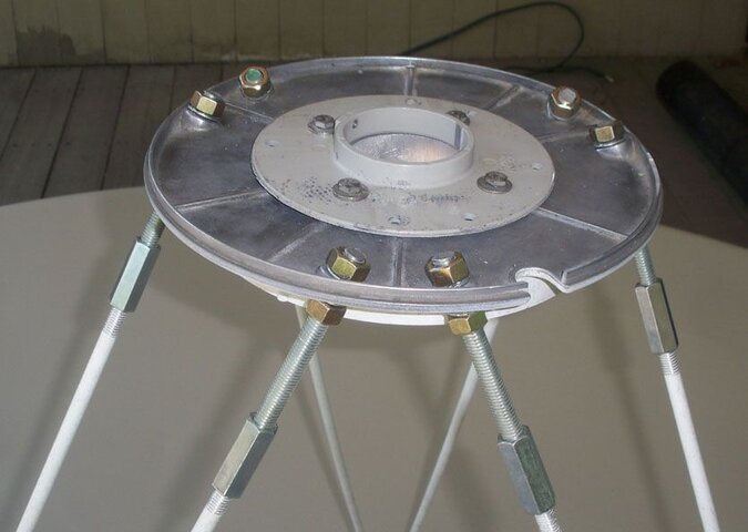
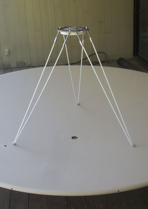
I decided not to model the feed for now, and instead have made several approximate calculations that I will validate when the dish goes up. I decided to add some threaded rod at the end of the existing struts to allow a fair amount of adjustment latitude for tweaking the focal length. The stock struts are about 43", with around 0.5" on each end for threads. I cut mine down to 40.25" and added 4.75" of threaded rod. This is coupled with an extender as shown in the photo. I've also shown an unmodified strut, an exploded view and an assembled unit. While the rod isn't really thick enough for a full set of threads, I decided to thread it as 7/16"-14. That was easy to cut and provides a solid fit. This means the scalar's strut holes will need to be enlarged and nuts installed on either side to set the distance for each rod.

04 Scalar Adapter

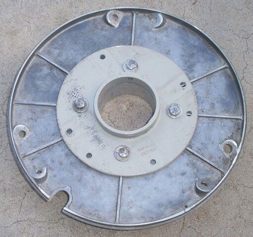
This is similar to what many others have done. The stock Birdview scalar has a hole too small for modern feeds, but is easily reamed out. I then took a spare modern scalar, cut the rings off and attached it using the existing Birdview holes. This will clamp a modern feed. There were nubs on the Birdview scalar that I ground down to get the feed clamp as close to flush as I could. I also decided to drill and tap the mounting holes all the way through. I've calculated an initial feed projection of 8mm beyond the scalar rings for the dual ortho I want to start with. Tweaking the f/D will be interesting because the scalar is a different configuration than typical for modern feeds.

05 Encoder Mount
06 Drive & Encoder

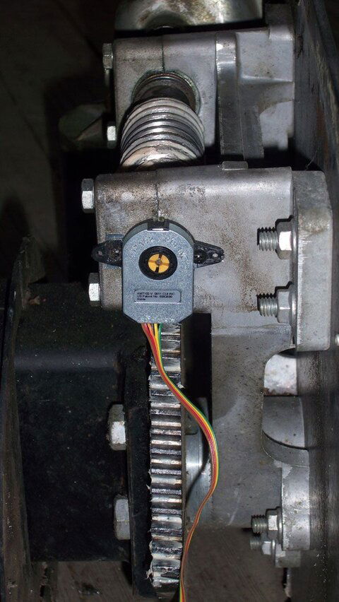
As I indicated in previous posts, the encoder is attached to a small shaft extending from the final drive's worm gear. I thought about this a lot and decided to use this particular mounting plate of the two supplied with the encoder. I had to use a thin shim to get the encoder perpendicular to the shaft. This appears rock solid and I'm getting consistent counting at an unbelievable rate. I still need to make the final circuit board and mount it inside the motor box.

07 Extended Pole

I need nearly 14' of pole to mount this beast to the house wall. Because of this chopping the original Birdview tube at ground level seemed the easiest option, as I was going to have to extend it anyway. As plhatwound had suggested, the Birdview 6" OD tube neatly fits into a 6" schedule 40 steel pipe. I had the scrap yard weld the two together after I ground off an enormous amount of rust on the bottom of the Birdview tube. I've also picked up a 6" OD to 6" steel pipe seal that I'll probably use on the roof as there will have to be a penetration. I've got three custom, grade 8 round U-bolts on the way for the primary mounting. At 6 5/8" in diameter, 18" long and a 7/8" thread, these should be quite impressive.

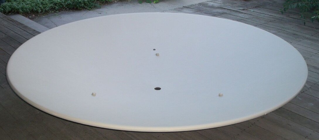
08 Painted Dish

I'm trying to be a good citizen and paint my dish to blend in with the wall that will extend up 16' behind it. This whole project has depended on reducing my house's nonconformance with a dish ordinance that was passed after I had my 15 dishes installed. The Birdview is replacing a 1.8m Fortec that has performed fairly well signal-wise, but has been a constant headache with the high winds we always get here. But I'll have to also sacrifice a 1.2m offset on a DG-380 motor to avoid having to deal with the Board of Appeals, which would be costly and offer no guarantee of success. That's a fair trade for me because the 1.2m/DG-380 is a complete joke even in a moderate breeze. I've got another 1.2m on a HH C-band motor that is a lot more rigid, to say nothing of a 1.8m Prodelin offset on a Ajak motor. With those and three toroid dishes covering nearly every Ku satellite visible in Denver, I'm not hurting for Ku coverage. With a little luck the dual ortho containing a universal Ku LNB, I may even get decent Ku performance out of the Birdview. I haven't used the DG-380 more than once in the past year and really won't miss it.
 

Attachments

  • 07 Extended Pole.jpg
    07 Extended Pole.jpg
    40.2 KB · Views: 353
  • 06 Drive & Encoder.jpg
    06 Drive & Encoder.jpg
    169.8 KB · Views: 338
  • 04 Scalar Adapter.jpg
    04 Scalar Adapter.jpg
    100.3 KB · Views: 342
  • 03 Strut Extension.jpg
    03 Strut Extension.jpg
    53.7 KB · Views: 307
  • 08 Painted Dish.jpg
    08 Painted Dish.jpg
    71.8 KB · Views: 310
  • 05 Encoder Mount.jpg
    05 Encoder Mount.jpg
    132.5 KB · Views: 327
Before painting the struts I assembled them to the dish and scalar. At the maximum extension, the distance from the dish center to the front of the scalar rings is 1.044m (41.1"). Allowing for my calculated feed protrusion and the likelihood the feed will perform best with the focal point inside by a few mm, this should work out fine. I wish I had cut the threaded rods a bit longer, but I could always replace them if they turn out too short.
 

Attachments

  • 10 Scalar Close-up.jpg
    10 Scalar Close-up.jpg
    77.6 KB · Views: 323
  • 09 Strut Dry Run.jpg
    09 Strut Dry Run.jpg
    70.6 KB · Views: 312
As I've said before, I find it hard to believe that a company as exacting as Birdview was, would approximate the focal length - so I am very interested in your focal length experiment.

I am not quite finished with my USALS skew project for my dual orthomode, and if that doesn't help me bring in S2 football feeds, I will be changing out my Technotrend card in favor something like a Prof. Now if that doesn't work either, I'll look at focal length.

Your modifications are pretty much the same as what I would try - Get the nuts off of the struts(without breaking them hopefully), get a small pipe wrench to hold the strut as I use a die on it to thread the strut. Extender nuts, etc.

If your focal length mod works, it will definitely be something I will keep in mind

LC, it is not a matter of conjecture that increasing your focal length on a BV will improve your signal, it has been proven time and again.

I do agree that it is weird that BV built them like that. If they had a reason for it I would like to know what it was.
 
Status
Please reply by conversation.

Users Who Are Viewing This Thread (Total: 0, Members: 0, Guests: 0)

Who Read This Thread (Total Members: 3)

Top