Splitters 101

Status
Please reply by conversation.

oncewaslost

SatelliteGuys Pro
Original poster
Feb 5, 2007
155
0
I purchased a hand full of splitters on ebay from a seller by the name of palmpdb.
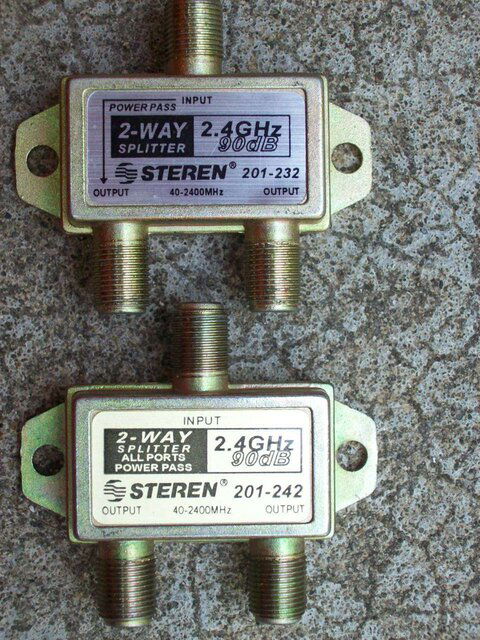
splitter.jpg
The one on the top is one port pass. It will pass voltage from the in port to the out port in the direction of the arrow. It will also pass voltage from that same out port to the in port backwards from the arrow. It will not pass voltage from the in port to the other out port in either direction. OK... as I expect.

The one on the bottom is an all port pass. It will not pass any voltage from the in port to either of the outs ports. It will pass voltage from both out ports to the in port. NOT...as I expect.

Before I go on a rant, Do you think this is normal for the "splitter" as it is labeled?
 
I'm kind of stupid about this, so please bear with me...

How would you use a splitter in an FTA setup as opposed to a DIsEQ switch or a multiswitch?

In my cable TV days, or my OTA days, there was no need to pass voltage through a splitter...

I'd like someone to explain this issue, please ...

Edit: Power versus voltage....
 
I'm kind of stupid about this, so please bear with me...

How would you use a splitter in an FTA setup as opposed to a DIsEQ switch or a multiswitch?

In my cable TV days, or my OTA days, there was no need to pass power through a splitter...

I'd like someone to explain this issue, please ...

Read this thread for an explanation for what I wanted it for. You will understand why it will not work for me.
http://www.satelliteguys.us/free-air-pc-dvb-discussion/141528-sg2100-insertion-loss.html

I am also able to use them with stacked lnb's. (one port passing)
 
How would you use a splitter in an FTA setup as opposed to a DIsEQ switch or a multiswitch?

reasons to use a splitter
-folks that have an old LNB on a C-Band dish can only see one polarity at a time (that is how they are set up) so a splitter works in place of a multiswitch (see this for more details)
-you have a bandstakced LNB which has both polarities on one side (vertical)....splitters work fine in this case so more than one receiver can see the satellite
-you have a single output LNB and want to run 2 boxes off a single satellite that has most channels on one polarity (G10 V for example)...splitters work in this case just fine

diseqc allows you to have up to 4 LNB's off one receiver
 
The one on the top is one port pass.
It will pass voltage from the in port to the out port in the direction of the arrow.
It will also pass voltage from that same out port to the in port backwards from the arrow.
It will not pass voltage from the in port to the other out port in either direction.
OK... as I expect.
Code:
[FONT=Fixedsys]..
Possible Schematic:
          
          ------------o  Power Pass side
          |
          |
o---------+
          |  small high-frequency-passing capacitor
          |   | |
          ----| |-----o
              | |
..[/FONT]
The one on the bottom is an all port pass.
It will not pass any voltage from the in port to either of the outs ports.
It will pass voltage from both out ports to the in port.
NOT...as I expect.
Code:
[FONT=Fixedsys]..
Possible Schematic:
          
[/FONT][FONT=Fixedsys]              \ |
          ----|>|-----o
          |   / |[/FONT][FONT=Fixedsys]
          |
o---------+        diodes
          |          (cathode side)
          |   \ |
          ----|>|-----o
              / |
..[/FONT]
Before I go on a rant, Do you think this is normal for the "splitter" as it is labeled?
Yes, and I think in the second case, it should read more like:
"passes power from the single common port to each LNB port"
 
However----
Yes, and I think in the second case, it should read more like:
"passes power from the single common port to each LNB port"

I believe that the OP wanted to split before the motor with one OUT port going to the motor and the other OUT port going to the LNB. I think the splitter that he bought will NOT supply power to either the motor or the LNB.
Bob
 
I believe that the OP wanted to split before the motor with one OUT port going to the motor and the other OUT port going to the LNB. I think the splitter that he bought will NOT supply power to either the motor or the LNB.
Bob
Wes -
. . . . I wrote what I believed, not exactly what the OP said.
But I do agree that if "power" flows only from the two output ports to the input port , then it won't do him much good.
. . . and it would certainly be a strange splitter. - :)

Once -
Did you use an ohm meter, or hook up the equipment in question, and take readings?
Reason I ask, a receiver puts out 12/18 volts positive.
So, if you used that and checked to see if the voltage appeared at the LNB, so be it.
 
I believe that the OP wanted to split before the motor with one OUT port going to the motor and the other OUT port going to the LNB. I think the splitter that he bought will NOT supply power to either the motor or the LNB.
Bob

Yes, that is what I was trying to do.

Yes, and I think in the second case, it should read more like:
"passes power from the single common port to each LNB port"

I think that you misunderstood which direction that the power is passing. The diode is backwards in your drawing.


Once -
Did you use an ohm meter, or hook up the equipment in question, and take readings?
Reason I ask, a receiver puts out 12/18 volts positive.
So, if you used that and checked to see if the voltage appeared at the LNB, so be it.

Yes, after realizing that neither my motor or LNB was functioning at all, I checked for voltage with a multimeter. Only a few tenths of a volt is leaking through from the "in" to the "out". From the "out" to the "in" .4V are dropped. (13V in and 12.6V out)

To clear up any confusion with my terminology, When I say "from" and "to", the positive voltage from the receiver is at the "from".
 
Code:
[FONT=Fixedsys]..
Possible Schematic:
          
          ------------o  Power Pass side
          |
          |
o---------+
          |  small high-frequency-passing capacitor
          |   | |
          ----| |-----o
              | |
..[/FONT]
Code:
[FONT=Fixedsys]..
Possible Schematic:
          
[/FONT][FONT=Fixedsys]              \ |
          ----|>|-----o
          |   / |[/FONT][FONT=Fixedsys]
          |
o---------+        diodes
          |          (cathode side)
          |   \ |
          ----|>|-----o
              / |
..[/FONT]
Yes, and I think in the second case, it should read more like:
"passes power from the single common port to each LNB port"

The second schematic is correct, but your diodes are backward. The anodes would need to go toward the 2 outputs as the receivers are what's supplying the power and they'll supply a positive potential to the anodes which is what's needed for them to conduct. If one receiver is supplying +18v and the other +13v then the diode on the one supplying +18v will be properly forward biased and conduct. The diode going to the one supplying +13v would be reverse biased and not conduct as it would see +18v (from the other receiver) on it's cathode and +13v on it's anode making the cathode more positive than the anode and thus switching it off. What your missing here is that in regard to DC voltage for the LNB the 2 outputs are inputs and the input is the output, exactly opposite as the way the splitter passes RF.

. . . and it would certainly be a strange splitter. -

Not strange at all. This is exactly how "diode protected" splitters are supposed to work. Remember these are designed for the purpose of splitting the signal coming from a dish and feeding it to receivers, not to be used the other way around. The purpose of the splitter being designed this way to protect the receivers connected to it. Because satellite receivers send voltage down the coaxial cable for the LNB, it's necessary to either only allow one receiver to send voltage down the cable and block all others or use protecting diodes in this arrangement as doing otherwise would present a short to the LNB voltage supply of the receivers. This would obviously happen if one receiver was attempting to supply +18v and one +13v, but could also happen if both receivers were attempting to supply the same voltage unless their power supplies were supplying exactly the same voltage with no variation. Say for example on receiver supplies +18.1v and the other +19.1v, there's a potential difference there. It may be small but it the short between them is of a low enough resistance you could still possibly get enough current flow to perhaps do damage.

Anyway, the problem here is your trying to use a splitter to do something it's not designed to do. Splitters are designed to split the signal between receivers. They're not designed to split the DC voltage between an LNB and motor. For that you'll need something different. You might be able to accomplished what your trying to do by taking a power inserter circuit and modifying it by removing the blocking capacitor and the power source and hooking the motor in where the power source would go. There would be an inductor between the power source and the center conductor of the transmission line. That inductor presents a high impedance to the RF and a low resistance to the DC isolating the power source from the RF. Youd want to hook the motor to that inductor where the power supply would normally connect. Youd also need to remove, and bypass, any DC blocking capacitors on the line going back to the receiver.
 
Last edited:
clarification

Yes, I drew the diodes backward from what Once said , on purpose.
I drew them in a manner which would work for his problem.
The part he has on-hand would therefore not work with the motor
 
I drew them in a manner which would work for his problem.

But the problem is that wouldn't work or at least wouldn't work very well and would cause signal problems. First of all it would probably cause impedance issues as a real splitter contains more than just diodes. It contains circuitry to maintain the proper impedance. Secondly if you designed it properly so that the impedance was properly matched you'd still be splitting your RF signal and sending half of it into the motor, which is totally unnecessary and would weaken your signal. As I said in my previous post the best way to design something to do this would be to start with the circuit a DC power inserter uses and modify it to make it kinda operate in reverse as a power separator.

Anyway, the real question that needs to be asked here is why does he want to do this. If it's to avoid the insertion loss of the motor, then it's probably a misguided effort as whatever you come up with to accomplish the goal will also have some insertion loss as well and if it's not designed properly could have much more loss than the motor would.
 
Yes, Indeed.
I already sort of knew why he got the parts.
So, the comments were slanted toward his intended goal.
And, I wasn't giving design info on building your own (not in this thread, anyway) :cool:

In fact, I'd already given a much better answer in the Insertion Loss in 2100 Motors thread, as wescopc mentioned above.
These comments would probably have been less confusing if they'd been part of that thread, but since I knew what Once was up to, it didn't matter to me. - :rolleyes:

Hard to keep up without a scorecard. - :D

Anole,

I do appreciate all of your input. The other thread made it sound like such an easy solution, and it still may be.

I am about to abandon the project for something that will produce more fruit.

Thanks!
 
Status
Please reply by conversation.

Users Who Are Viewing This Thread (Total: 0, Members: 0, Guests: 0)

Who Read This Thread (Total Members: 1)

Latest posts