I have a bud and have used actuator without sensor hooked up every way I have tried wiring it doesnt work I pulled cap off back and there is no name on it anywhere just a date of 1985

can anybody identify this actuator and sensor
- Thread starter lance007
- Start date
- Latest activity Latest activity:
- Replies 49
- Views 6K
You are using an out of date browser. It may not display this or other websites correctly.
You should upgrade or use an alternative browser.
You should upgrade or use an alternative browser.
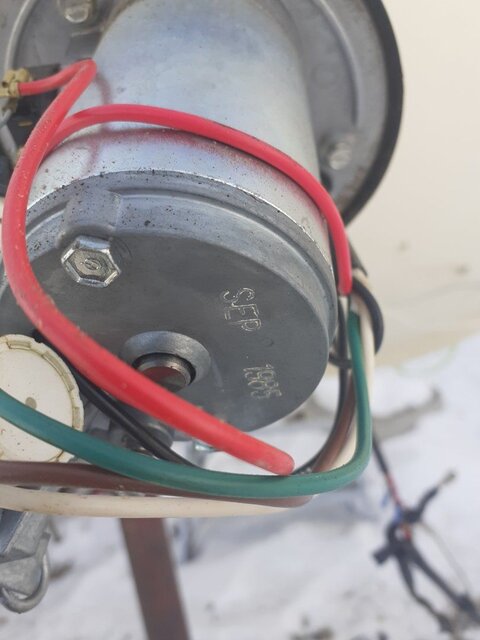
That's a potentiometer type sensor. There are no controllers available to use that sensor. You need a new actuator or design and make a reed switch sensor for it.
I thought I saw everyone, but now that one, but my gut says sticky brushes hit the side hard near the back of motor with a block of wood with power on if it moves that's it, also put an ohmmeter on it if it reads open the brushes need lube if it reads 2-12 ohm it's a mech issue fix that with PB blasterI have a bud and have used actuator without sensor hooked up every way I have tried wiring it doesnt work I pulled cap off back and there is no name on it anywhere just a date of 1985
Tear down the motor. Clean it up. Motor brushes still have lots of life? Bushings (bearings) in good shape?
What happens when you put voltage directly on the leads running into the motor?
That way you'll bypass the diodes and limit switches.
Speaking of, diodes must be checked on multimeter diode check. Not just ohms.
You'll probably have to unsolder a lead to do that. Also just because a limit switch checks okay with a meter doesn't mean the contacts aren't sinking the motor load.
And smacking the motor case isn't a good idea. I've seen motors (super-crap) that the magnets which have become unglued worse than the wifey when you come home at 3am doya.
the actuator moves just mine but I have to manually step it with remote e or w .
my old uniden sq560 only lists hall sensor and Reed and optic so I guess I'm sol.
how would I convert it to Reed sensor also were would I buy 1
my old uniden sq560 only lists hall sensor and Reed and optic so I guess I'm sol.
how would I convert it to Reed sensor also were would I buy 1
PLEASE LOG IN TO GET RID OF THESE ADS!
dish moves fine I just dont have any countsI thought I saw everyone, but now that one, but my gut says sticky brushes hit the side hard near the back of motor with a block of wood with power on if it moves that's it, also put an ohmmeter on it if it reads open the brushes need lube if it reads 2-12 ohm it's a mech issue fix that with PB blaster
how would I go about doing this it works fine but wish I could program sat positionsThat's a potentiometer type sensor. There are no controllers available to use that sensor. You need a new actuator or design and make a reed switch sensor for it.
Switching an optical or hall effect sensor to a reed switch is fairly easy. But changing a potentiometer is a different ball game. There is no blueprint for any of that to follow so it comes totally from your own skills and imagination. The best way is to find a different actuator with a reed switch.

if you have access to a 3d printer it's quite easy to make a magnet wheel. The tough part is figuring out how to mount it to that actuator. Is there any spot that gives easy access to the actual actuator shaft? A reed switch should not be too difficult to find.
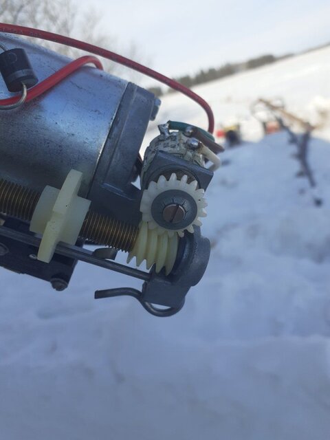
Can you post more pictures of that actuator? Particularly of the gears and other mechanical parts connecting the motor to the screw.
Can you post more pictures of that actuator? Particularly of the gears and other mechanical parts connecting the motor to the screw.
PLEASE LOG IN TO GET RID OF THESE ADS!
Wished you lived closer and brought a couple of 6 packs. I'd ace it out for you in a couple hours most. Hall or reed.
What I'd do to convert it is mark out 4-8 sections on the helical gear perimeter and bore it to sink in small neodymium magnets.
Then rob an old PC fan for the hall sensor. Cut a chunk of plastic and heat bend it to let me epoxy the sensor on so there was about a nickel spacing between it and the magnet. Yank the potentiometer and use that hole to mount my hall bracket to.
3 wires from the hall to your terminal block and you'd probably be golden.
I did a similar thing to my super-crap actuator but used an old vcr gear to put 20 magnets on with alternating opposing poles.
Poles with alternating N-S for a definite on/off snap action of the hall sensor.
Works like a peach with 10ppr an an ASC1. I could pop the cover and snap a photo if you'd like.
thanks I am a mechanic so wiring and rigging isint a problem but I got my eye on two other buds that clearly are not being used in yrs in wpg Canada were I live so probably just gonna pick up one or bothWished you lived closer and brought a couple of 6 packs. I'd ace it out for you in a couple hours most. Hall or reed.
What I'd do to convert it is mark out 4-8 sections on the helical gear perimeter and bore it to sink in small neodymium magnets.
Then rob an old PC fan for the hall sensor. Cut a chunk of plastic and heat bend it to let me epoxy the sensor on so there was about a nickel spacing between it and the magnet. Yank the potentiometer and use that hole to mount my hall bracket to.
3 wires from the hall to your terminal block and you'd probably be golden.
I did a similar thing to my super-crap actuator but used an old vcr gear to put 20 magnets on with alternating opposing poles.
Poles with alternating N-S for a definite on/off snap action of the hall sensor.
Works like a peach with 10ppr an an ASC1. I could pop the cover and snap a photo if you'd like.
I was thinking about this before even posting I was thinking attach magnets to potentiometer gear and fabricating a steel bracket to hold a hall or reed sensor how many counts does it need tho 60 or 30 or so onWished you lived closer and brought a couple of 6 packs. I'd ace it out for you in a couple hours most. Hall or reed.
What I'd do to convert it is mark out 4-8 sections on the helical gear perimeter and bore it to sink in small neodymium magnets.
Then rob an old PC fan for the hall sensor. Cut a chunk of plastic and heat bend it to let me epoxy the sensor on so there was about a nickel spacing between it and the magnet. Yank the potentiometer and use that hole to mount my hall bracket to.
3 wires from the hall to your terminal block and you'd probably be golden.
I did a similar thing to my super-crap actuator but used an old vcr gear to put 20 magnets on with alternating opposing poles.
Poles with alternating N-S for a definite on/off snap action of the hall sensor.
Works like a peach with 10ppr an an ASC1. I could pop the cover and snap a photo if you'd like.
A typical actuator has a 4 magnet wheel that turns on a 8 pitch threaded shaft. Equals 32 counts per inch of actuator travel. Others have a 8 magnet wheel and a 5 pitch threaded shaft. 40 counts per inch. So a 24" actuator can turn the magnet wheel 120 times over the travel. Now the potentiometer shaft turns once to that 120 turns of a reed switch type. Now you see why converting a potentiometer sensor presents a challenge. You need a whole new drive system for the sensor.
To Lance and Magic and others.
I don't really know about how many pulses/inch but here looking at my log sheet I'm seeing that with basically the 10 magnet deal I fashioned up I'm getting 32pulses (counts on the ASC1) per 2 degrees.
There are actually 20 magnets on the disc. The alternating South pole magnets serve for a definite turn-off, or open collector 'snap action ' of the hall device. Looks awesome on the 'scope. Work for you Magic?
The hall device actually has N-S sensing so I think with a pair of diodes I could actually double my counts.
An improvement from the original 6 sector magnet that was giving me 26ppr.
It makes calculating the next sat in the arc when transponder searching and storing positions in the dish mover easier and more accurate.
There's enough slop in the super jack that I still have to tweak the position several counts here and there in the arc.The pulse disc is coming right off of the actuator drive. What would be the first step is to determine the resolution of the worm gear that drives the pot gear. I haven't see a pot setup on an actuator to tell if it's a single or multi turn unit.
If it's a single turn unit you might as well wash the whole idea. Because you'll probably never get the resolution needed to accurately move the dish to position (ex: 3 pulses between 101 & 103 just aint gonna' do it).
PLEASE LOG IN TO GET RID OF THESE ADS!
I make high resolution sensors for my AJAK H~H mounts. I use a 10 magnet wheel. All magnets polarized the same direction. I use a magnetic glass reed switch oriented so each magnet is counted twice. This gives me 20 counts per degree or accuracy to .025 of a degree. ")
Love to see those picturesif you have access to a 3d printer it's quite easy to make a magnet wheel. The tough part is figuring out how to mount it to that actuator. Is there any spot that gives easy access to the actual actuator shaft? A reed switch should not be too difficult to find.
Can you post more pictures of that actuator? Particularly of the gears and other mechanical parts connecting the motor to the screw.
I think its a ten turn pot , attaching the pulswheel direct to the threaded shaft will bring more pulses / inch actuator movement .A typical actuator has a 4 magnet wheel that turns on a 8 pitch threaded shaft. Equals 32 counts per inch of actuator travel. Others have a 8 magnet wheel and a 5 pitch threaded shaft. 40 counts per inch. So a 24" actuator can turn the magnet wheel 120 times over the travel. Now the potentiometer shaft turns once to that 120 turns of a reed switch type. Now you see why converting a potentiometer sensor presents a challenge. You need a whole new drive system for the sensor.
This would do it then. Had them in industrial machines up to 1024 p/r.
At 100 p/r for a 10 turn pot replacement you would get 1000 pulses.
Did the math. I'm looking at 133W to 47.5W at 1038 pulses/counts.
My West limit switch is at 20 and the screw turned out 5 turns from from its hard limit of "oops no more threads".
133 is positioned at 143 counts. 47.5 is at 1038. Dish flop happens shortly after that so the East limit is, oh, 1050.
The encoder physically resembles a pot with a shaft flat for a set screw. Look at US Digital's site for documentation.
S1-100-IB US Digital Optical Rotary Encoder Brand New 100CPR | eBay
Find many great new & used options and get the best deals for S1-100-IB US Digital Optical Rotary Encoder Brand New 100CPR at the best online prices at eBay! Free shipping for many products!
www.ebay.com
PLEASE LOG IN TO GET RID OF THESE ADS!
Similar threads
- Replies
- 2
- Views
- 75
- Replies
- 0
- Views
- 797
- Replies
- 0
- Views
- 605
- Replies
- 0
- Views
- 703